
Mechanical loading creep age forming device

A creep aging forming and mechanical loading technology, applied in the field of aerospace manufacturing engineering, can solve the problems of easy internal damage of parts to be formed, poor forming adaptability of multi-curvature parts, inconvenient automatic control, etc. The effect of time, simple structure and high practicability

Pending Publication Date: 2020-03-24
CENT SOUTH UNIV
View PDF2 Cites 10 Cited by
  • Summary
  • Abstract
  • Description
  • Claims
  • Application Information

AI Technical Summary

Problems solved by technology

Chinese invention patent CN102266887B discloses a mold-shaped plate-type mechanically loaded creep aging forming device. The upper mold adopts a dot-matrix loading method to rise and fall, the structure is complicated, and it is inconvenient for automatic control, and the pillar and the workpiece are in point contact. Formed parts are prone to internal damage; the lower die adopts a mold-shaped plate type, which is not easy to repair and has poor adaptability to the forming of multi-curvature parts
Chinese invention patent application CN110052520A discloses a combined mechanically loaded creep aging forming device, in which the punch and die are hinged by a plurality of two-way die-shaped plate connection units; in the loading state, the middle part of the punch and die is combined The shape of the curved surface of the mold plate is not easy to control, and it is difficult to ensure that the shape of the die is the target surface

Method used


Image

  • Mechanical loading creep age forming device
  • Mechanical loading creep age forming device
  • Mechanical loading creep age forming device

Examples


Embodiment Construction

[0032] The embodiments of the present invention will be described in detail below with reference to the accompanying drawings, but the present invention can be implemented in various ways defined and covered by the claims.

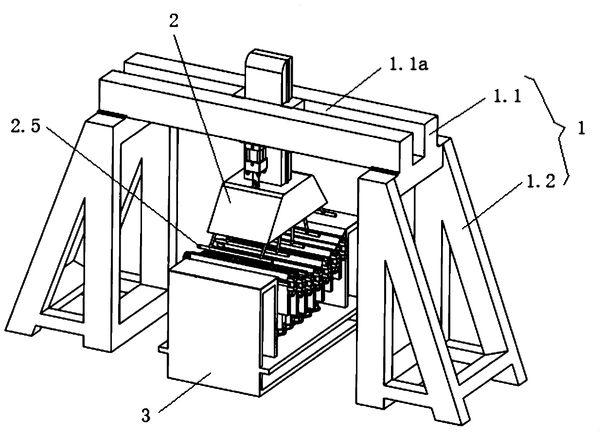
[0033] see figure 1 , a mechanically loaded creep aging forming device, comprising a frame 1, a loading device 2 and a mold 3, the loading device is arranged on the frame, and the mold is arranged below the loading device. The specific structure is: the frame includes a crossbeam 1.1 and legs 1.2 arranged at the bottom of both ends of the crossbeam, the crossbeam is provided with a through hole arranged along the vertical direction, and the top of the crossbeam is provided with a groove 1.1a arranged along its length direction.

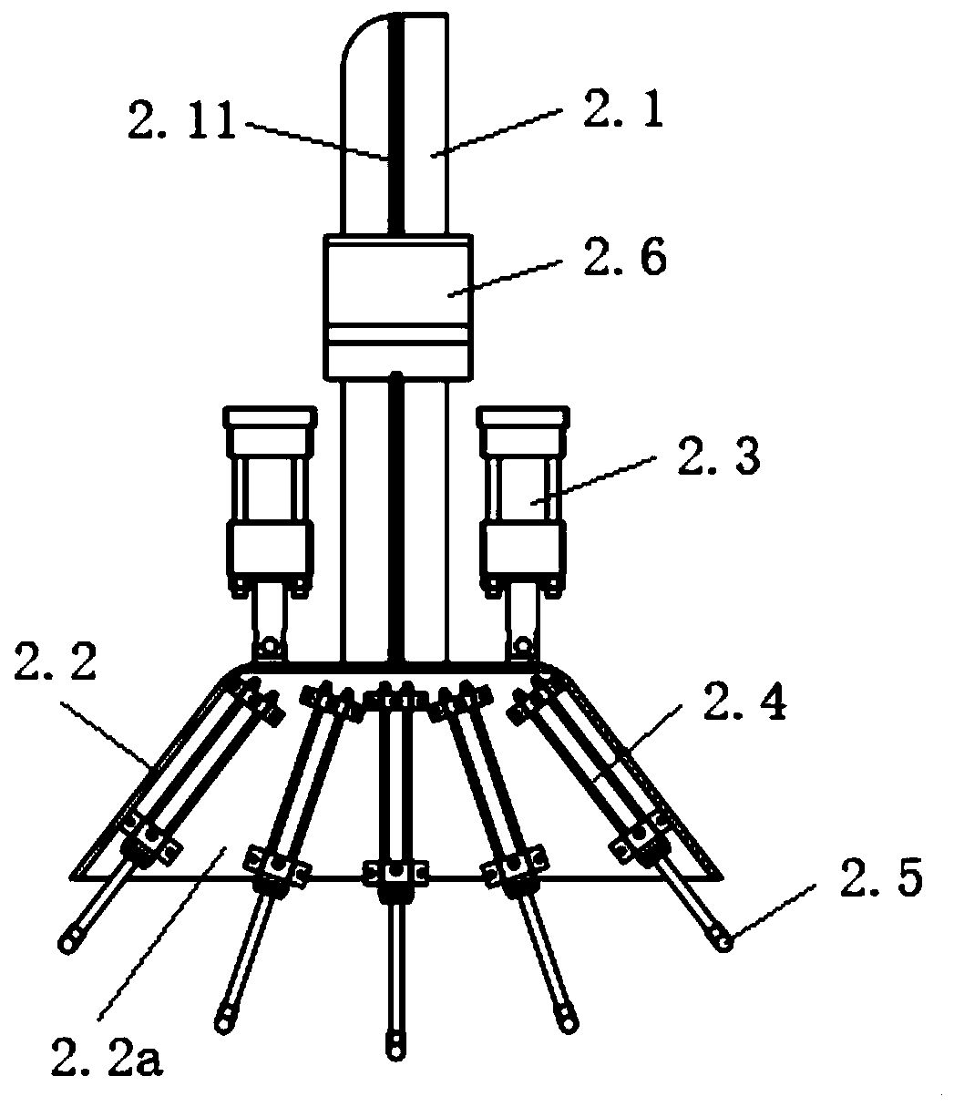
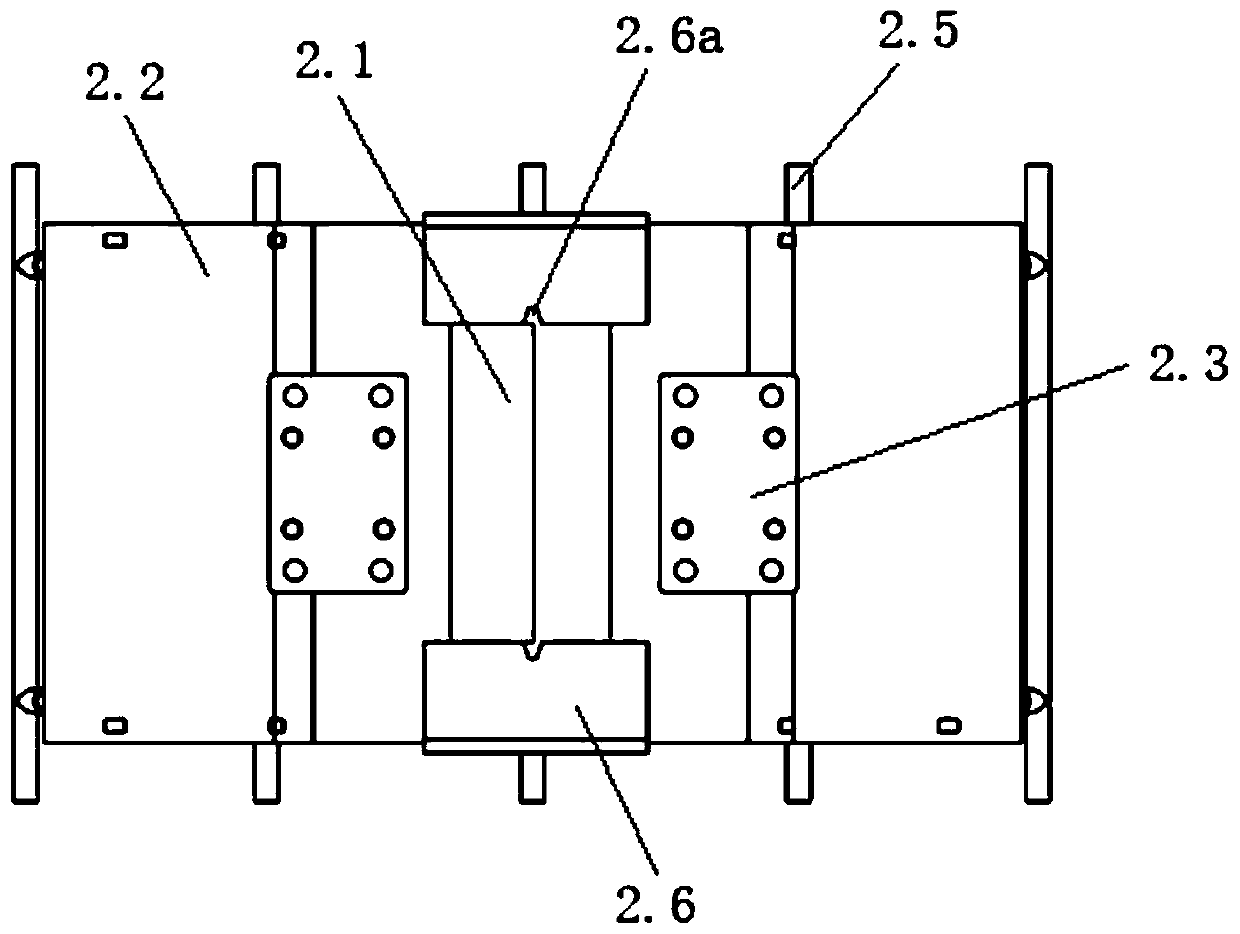
[0034] combine Figure 2 to Figure 4As shown, the loading device 2 includes a guide rod 2.1, a skirt bracket 2.2, a main hydraulic cylinder 2.3 and multiple sets of loading hydraulic cylinders 2.4. The inside of the bracket is p...


PUM


Abstract

The invention discloses a mechanical loading creep age forming device. The mechanical loading creep age forming device comprises a rack, a loading device arranged on the rack and a mold arranged belowthe loading device; the loading device comprises a plurality of groups of loading hydraulic cylinders; the extending directions of the piston rods of two adjacent groups of loading hydraulic cylinders are different; the extending directions of the piston rods of the plurality of loading hydraulic cylinders in the same group are identical, and the lower ends of the plurality of piston rods are jointly connected with a pressing rod; and the mold comprises a mold-shaped plate and a plurality of supporting devices for supporting the mold-shaped plate. According to the mechanical loading creep ageforming device, the telescopic lengths of the piston rods of the different groups of loading hydraulic cylinders are controlled; the heights of the supporting devices can be adjusted, so that the curvature of a mold profile is adjusted; and therefore, the forming device can form multiple workpieces with different curvatures; a loading force is applied to a to-be-formed workpiece through the pressing rod, so that the possibility that internal defects are generated in the workpiece in a loading process is reduced. The mechanical loading creep age forming device has the advantages of simple structure, high operability, high practicability and stable quality of the formed workpiece.

Description

technical field [0001] The invention relates to the technical field of aerospace manufacturing engineering, in particular to a mechanically loaded creep aging forming device. Background technique [0002] With the development of aluminum alloy integral wall panels in the direction of large curvature, high-strength thin skin, traditional room temperature forming methods such as gate pressing, rolling bending, stretching, and shot blasting can no longer meet the precise shape manufacturing requirements of integral wall panels. As a processing method suitable for the forming of aluminum alloy integral panels, creep aging forming is based on the characteristics of material creep and aging, and combines aging heat treatment and forming process to simultaneously realize the forming of the shape and performance requirements of the part. craft. First of all, the workpiece is elastically deformed by a certain loading method at room temperature, and this deformation is maintained; th...

Claims


Application Information

Patent Timeline
IPC IPC(8): B21D31/00C21D8/00C22F1/04
CPCB21D31/00C21D8/00C22F1/04
Inventor 湛利华彭南辉徐永谦杨有良
Owner CENT SOUTH UNIV
Learn More