66kV in-field submarine cable processing auxiliary cutting equipment for offshore wind power generation

A 66kv, submarine cable technology, used in the field of auxiliary cutting equipment for 66kV in-field submarine cable processing for offshore wind power generation, can solve the problems of unstable force at the cutting point, poor cutting effect, and poor neatness of the cutting surface. The effect of cutting quality, easy maintenance and low equipment cost

Active Publication Date: 2020-03-24
ANHUI STAR CABLE
6 Cites 2 Cited by

AI-Extracted Technical Summary

Problems solved by technology

The disadvantage is that when the device is actually used, the cable can only be fixed in a single way, and the cutting point is still in a ...

Abstract

The invention relates to 66kV in-field submarine cable processing auxiliary cutting equipment for offshore wind power generation. The equipment comprises a frame body and two mounting plates distributed on the frame body along the same center line, and clamping mechanisms are slidably mounted on the two mounting plates along the same center line. The frame body is provided with a first driving mechanism used for driving the clamping mechanisms to clamp and fix a cable, and a second driving mechanism used for enabling the clamping mechanism to do opposite motion to tension and straighten the cable after the clamping mechanisms fixe the cable. By means of the clamping mechanisms, the first driving mechanism and the second driving mechanism, the cable is clamped and fixed firstly and then tensioned and straightened in the opposite direction, so that the cutting effect and the cutting quality are greatly improved; by designing an offsetting assembly, the situation that the cutting effect is affected due to loosening, clamping and fixing of the cable in the tensioning process is avoided; and in addition, compared with an existing cable cutting device, the cable cutting device is simplein structure, low in equipment cost, small in occupied area and easy to maintain.

Technology Topic

Image

  • 66kV in-field submarine cable processing auxiliary cutting equipment for offshore wind power generation
  • 66kV in-field submarine cable processing auxiliary cutting equipment for offshore wind power generation
  • 66kV in-field submarine cable processing auxiliary cutting equipment for offshore wind power generation

Examples

  • Experimental program(1)

Example Embodiment

[0024] In order to make the technical means, creative features, objectives and effects of the present invention easy to understand, the present invention will be further described below with reference to the accompanying drawings and embodiments.
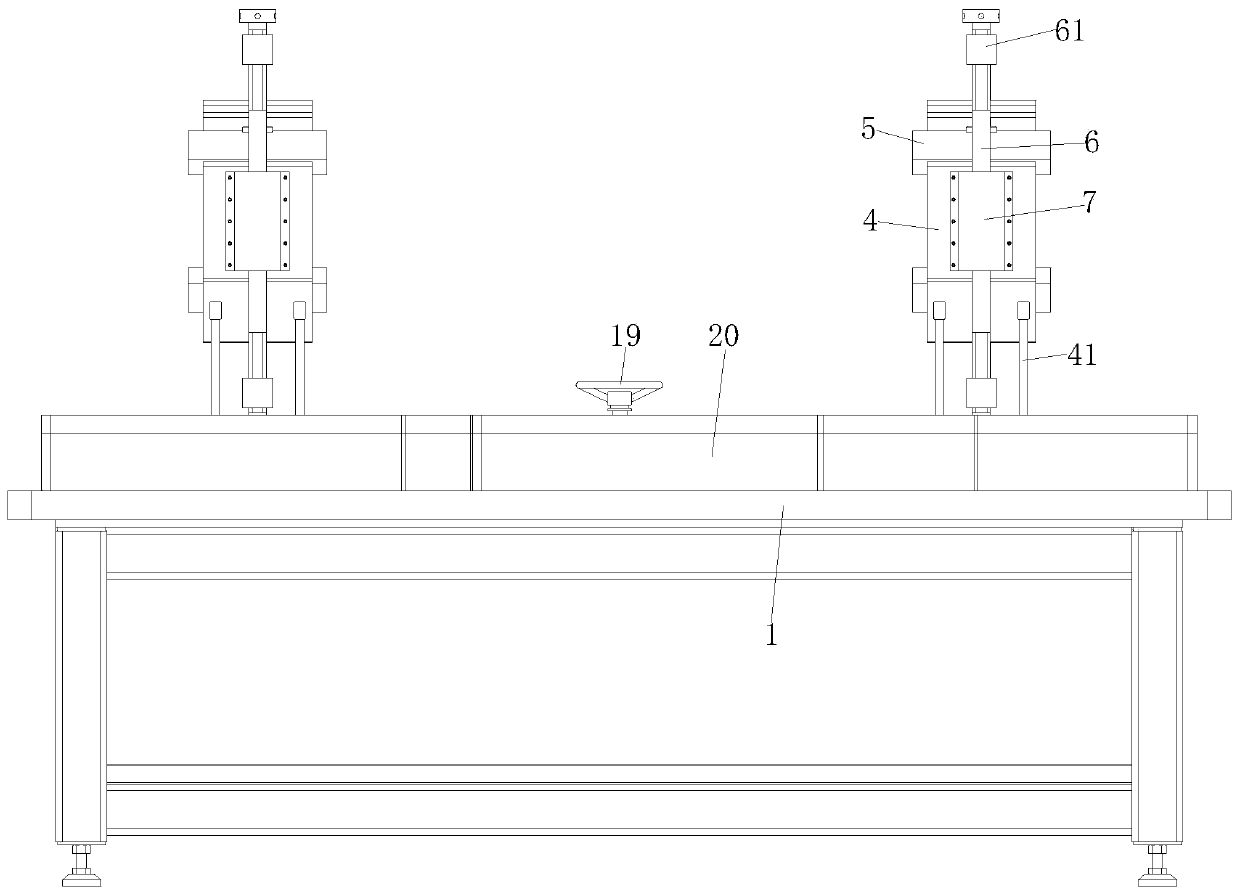
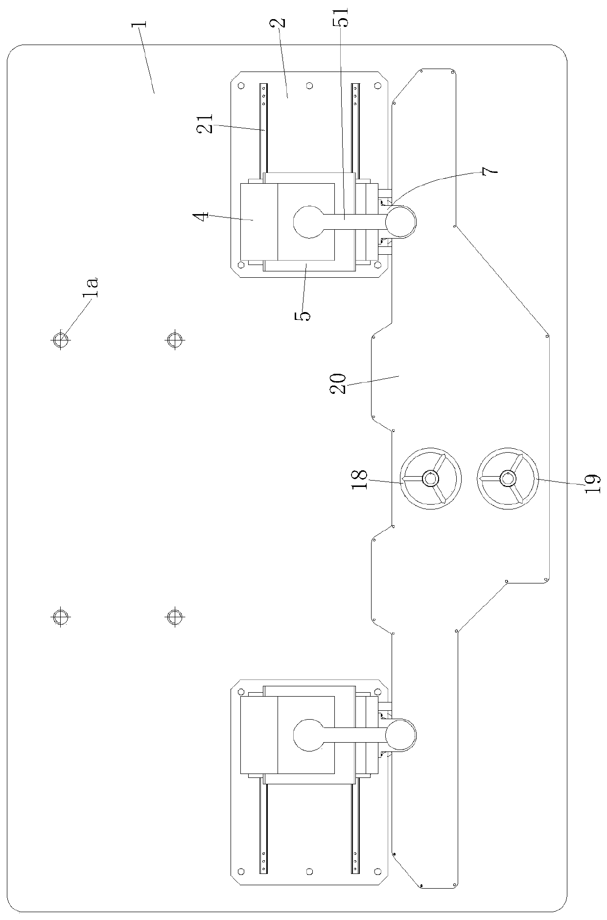
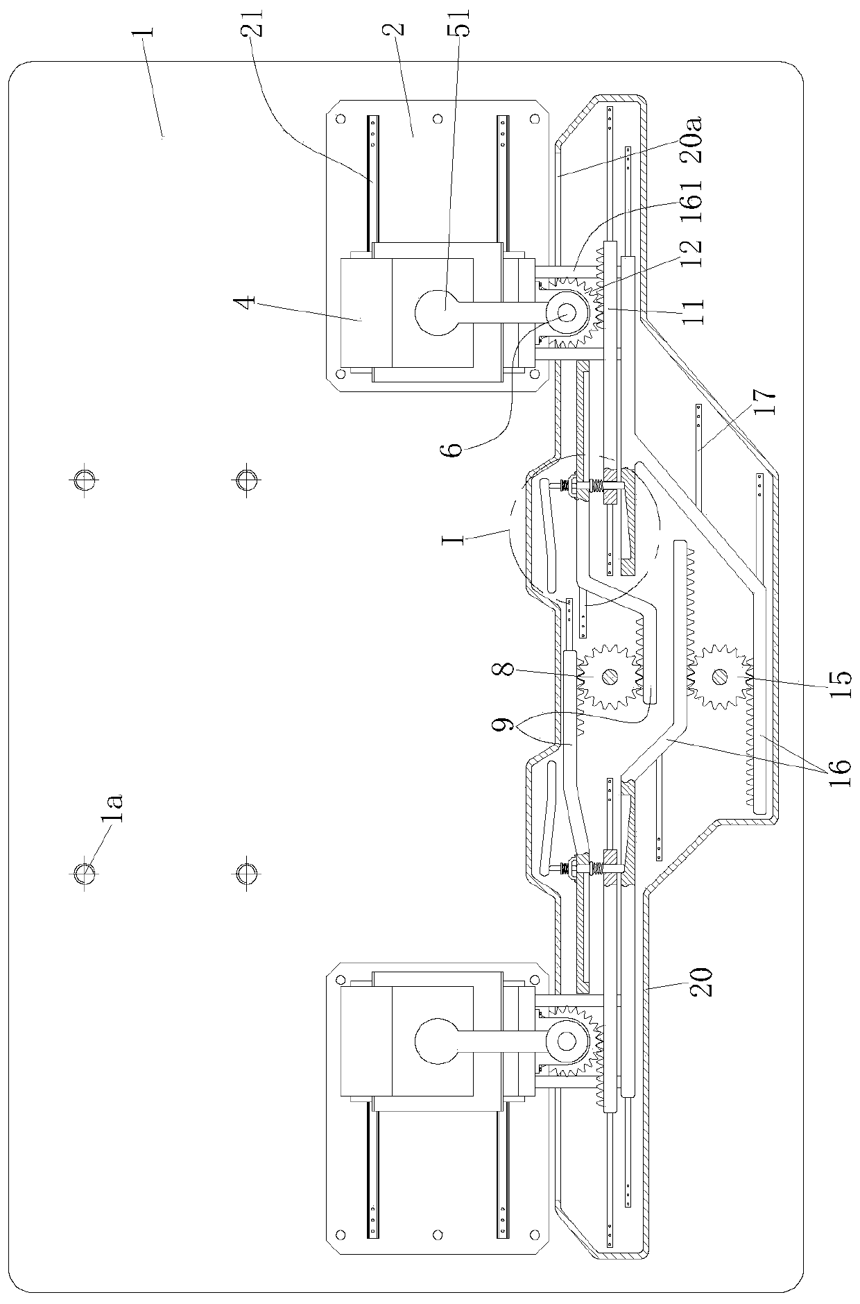
[0025] Such as Figure 1 to Figure 5 As shown, the auxiliary cutting equipment for submarine cable processing in the 66kV field for offshore wind power generation includes a frame body 1. The upper end of the frame body 1 is provided with a platform, and two platforms are provided on the platform along the left and right directions and on the same centerline. There are two mounting plates 2, and each mounting plate 2 is fixedly installed on the platform by screws. Each mounting plate 2 is slidably equipped with a clamping mechanism, and the two clamping mechanisms are also on the same center line.
[0026] Such as figure 1 , figure 2 with image 3 As shown, the front side of the platform of the frame body 1 is provided with a protective casing 20, and the rear side of the platform of the frame body 1 is provided with four threaded mounting holes 1a for fixing the cutting device. The protective casing 20 is provided with a first driving mechanism for driving the clamping mechanism to clamp and fix the cable, and a second driving mechanism for tightening the cable by making the clamping mechanism move in the opposite direction after the clamping mechanism fixes the cable. The second driving mechanism, wherein the first driving mechanism and the second driving mechanism are distributed in the front and rear direction, the first driving mechanism is behind, and the second driving mechanism is in front.
[0027] A first hand wheel 18 and a second hand wheel 19 corresponding to the first driving mechanism and the second driving mechanism are respectively provided above the protective casing 20, which are driven by manually rotating the first hand wheel 18 and the second hand wheel 19 The first driving mechanism and the second driving mechanism work. The protective casing 20 is divided into two parts: a casing body and a casing cover. The casing cover is installed on the casing body by screws. The function of the protective casing 20 is to prevent dust and cable debris from falling into the The first driving mechanism and the second driving mechanism also serve the purpose of protecting the safety of operators.
[0028] Such as image 3 with Figure 5 As shown, the clamping mechanism includes a sliding plate 3, a clamping bracket 4 fixedly mounted on the sliding plate 3 through a plurality of support rods 41, a sliding rail 21 is provided on the mounting plate 2 along the left and right directions, and the sliding plate 3 The sliding block 31 provided at the bottom is slidably mounted on the No. 1 slide rail 21. Two movable grippers 5 are symmetrically provided on the upper and bottom of the clamping bracket 4, and the ends of the two movable grippers 5 are both provided There is a bearing connecting rod 51, and the clamping parts of the two movable grippers 5 are provided with rubber friction pads 52 for increasing friction.
[0029] A bearing seat 7 is provided on the front side wall of the clamping bracket 4, and a vertically distributed double-ended screw 6 is arranged in the bearing seat 7, and both ends of the double-ended screw 6 are covered with screw nuts 61. The bearing connecting rod 51 is correspondingly connected with the screw nut 61 by bolts, and the lower end of the double-ended screw 6 is connected with the first driving mechanism.
[0030] Such as image 3 with Figure 4 As shown, the first driving mechanism includes a first rotating gear 8 installed on the platform of the frame 1 through a bearing seat and coaxially connected with the first hand wheel 18, and distributed on both sides of the first rotating gear 8 and meshing with it. The two racks A9, two symmetrically distributed racks B11, and a gear B12 coaxially installed at the lower end of the double-ended screw 6 and meshing with the rack B11.
[0031] Each rack A9 is provided with a sliding groove 91 distributed in the left-right direction. The sliding groove 91 is provided with a through hole 9a at the end near the first rotating gear 8, and the end of the gear B12 is provided with A slidable elastic pin 10, the end of the elastic pin 10 is inserted into the through hole 9a to achieve a fixed connection between the rack A9 and the rack B11, and the elastic pin 10 is on and located between the rack A9 and the rack B11 There is a spring 101 around it.
[0032] Each rack A9 is provided with an abutting elastic pin 10 on the rear side of the through hole 9a to make the rack B11 and the rack A9 change from a fixed connection relationship to a sliding fitting relationship; the offset assembly It includes a guide rod fixing seat 142 fixedly installed on the rear side wall of the rack A9, and a track board 13 arranged on the rear side of the rack A9 and located on the platform of the frame 1. The guide rod fixing seat 142 is provided with a corresponding sliding An elastic abutment pin 14 that abuts with the end of the elastic pin 10 and the other end abuts with the front side wall of the track plate 13 is on the elastic abutment pin 14 and between the guide rod fixing seat 142 and the rear side wall of the rack A9 There is a second spring 141 around it. Both the No. 1 spring 101 and the No. 2 spring 141 play a reset function.
[0033] Such as image 3 with Figure 4 As shown, the second driving mechanism includes a second rotating gear 15 mounted on the platform of the frame 1 through a bearing seat, and two racks C16 that are distributed on both sides of the second rotating gear 15 and meshed with it; The bottoms of the bar A9, the rack B11, and the rack C16 are all provided with No. 2 sliding rails 17 distributed in the left-right direction. The two racks C16 are respectively fixedly connected to the two sliding plates 3 through the connecting rod 161, and each rack C16 is provided with an oblique groove 16a slidingly fitted with the corresponding elastic pin 10, and the bottom of the oblique groove 16a The purpose of the inclined structure is to adapt to the change in the length of the elastic pin 10 caused by the elastic abutment pin 14 when it is moved by the rack A9.
[0034] Based on the above, when the rack A9 slides left and right, the elastic abutment pin 14 slides forward under the action of the track plate 13, and the elastic pin 10 located in the through hole 9a is pushed out. When the rack A9 slides a certain stroke After that, the elastic pin 10 is completely pushed out, and the end of the elastic abutting pin 14 is flush with the bottom of the sliding groove 91, that is, the elastic pin 10 is in the sliding groove 91, so that the rack A9 and the rack B11 are fixedly connected from the previous The relationship is transformed into a sliding fit relationship. At this time, one end of the elastic pin 10 is attached to the side wall of the inclined groove 16a. When the rack C16 moves, it will not only drive the sliding plate 3 and the clamping mechanism on the sliding plate 3 to move. The elastic pin 10 drives the rack B11 to move together. The purpose of this design is to ensure that the rack B11 and the gear B12 can remain relatively stationary, and prevent the gear B12 from meshing and rotating with the rack B11, driving the double-ended screw 6 to rotate, so that Move the gripper 5 to loosen the clamping and fixing of the cable.
[0035] work process:
[0036] Before use, the cutting device is fixed on the platform of the frame 1 through the threaded mounting hole 1a. Initially, the elastic pin 10 is inserted into the through hole 9a, the rack A9 and the rack B11 are in a fixed connection relationship, and the other end of the elastic pin 10 is slidably mounted in the inclined groove 16a.
[0037] Such as image 3 with Figure 4 As shown, the 66kV field submarine cable is passed from left to right or right to left through the clamping bracket 4 of the two clamping mechanisms and the cutting device in the middle.
[0038] Then, manually turn the first hand wheel 18 clockwise, through the first rotating gear 8 and the elastic pin 10, the two racks A9 drive the two corresponding racks B11 to slide in opposite directions and mesh with the two racks B11. The gear B12 rotates, through the double-ended screw 6, the movable grippers 5 of the two gripping mechanisms simultaneously perform opposite gripping actions to grip and fix the submarine cable in the 66kV field.
[0039] During the sliding of rack A9 and rack B11, under the action of the track plate 13, the elastic pin 14 gradually pushes the elastic pin 10 out of the through hole 9a. When the submarine cable in the 66kV field is completely clamped and fixed , The elastic pin 10 is completely pushed out and the end is located in the sliding groove 19; at this time, the rack A9 and the rack B11 transform from a fixed connection relationship to a sliding fitting relationship; at the same time, the other end of the elastic pin 10 and the inclined groove The side wall of the groove 16a is attached.
[0040] After the submarine cable is clamped and fixed in the 66kV field, manually turn the second hand wheel 19 counterclockwise, through the second rotating gear 15 and the connecting rod 16, the two racks C16 drive the sliding plate 3 to slide in the opposite direction, and then the clamped The 66kV field submarine cable was pulled in the opposite direction, so that the 66kV field submarine cable was stretched and straightened.
[0041] The rack C16 passes through the elastic pin 10 during the sliding process, and the rack B11 slides with the rack C16 in the same direction and at the same speed, so that the rack B11 and the gear B12 always remain relatively static, ensuring that the submarine cable in the 66kV field is stretched and straight. During the process, the submarine cable in the 66kV field was always clamped and fixed.
[0042] After the 66kV field submarine cable is stretched and straightened, the 66kV field submarine cable is cut by the cutting device.
[0043] The above shows and describes the basic principles, main features and advantages of the present invention. Those skilled in the industry should understand that the present invention is not limited by the above-mentioned embodiments. The above-mentioned embodiments and the specification describe only the principles of the present invention. Without departing from the spirit and scope of the present invention, the present invention will have various aspects. Various changes and improvements, these changes and improvements fall within the scope of the claimed invention. The scope of protection claimed by the present invention is defined by the appended claims and their equivalents.

PUM

no PUM

Description & Claims & Application Information

We can also present the details of the Description, Claims and Application information to help users get a comprehensive understanding of the technical details of the patent, such as background art, summary of invention, brief description of drawings, description of embodiments, and other original content. On the other hand, users can also determine the specific scope of protection of the technology through the list of claims; as well as understand the changes in the life cycle of the technology with the presentation of the patent timeline. Login to view more.

Similar technology patents

Dust removing and cutting device for building heat-preserving plate

InactiveCN107042535AImprove cutting effectAvoid problems such as scratchesBuilding repairsDirt cleaningLinear motor
Owner:SUZHOU YUXI NEW MATERIAL TECH

Classification and recommendation of technical efficacy words

  • Improve cut quality
  • Improve cutting effect

Pipe cutter

Owner:CEKA ELEKTROWERKZEUGE

Paper towel cutting mechanism

ActiveCN105996880AImprove cutting effectDomestic applicationsPaper towel
Owner:杭州迅行物联网科技有限公司

Plant trimming apparatus and methods

ActiveUS20190124851A1Improve cutting effectEasy to disassembleBud removersMowersAngular rangeLanding zone
Owner:ETEROS TECH INC
Why Eureka
Try Eureka