A method for forming a lightweight motor shaft

A molding method and motor shaft technology, which is applied in the field of shaft parts processing, can solve the problems of increasing the weight of the shaft, increasing the processing time, and increasing the diameter, and achieve the effects of improving utilization, high precision, and reducing self-weight

Active Publication Date: 2021-06-25
WUHAN UNIV OF SCI & TECH
View PDF8 Cites 0 Cited by
  • Summary
  • Abstract
  • Description
  • Claims
  • Application Information

AI Technical Summary

Problems solved by technology

Because the bearing moment of the motor shaft is very large, reaching 200-350N meters, the diameter of the motor shaft is relatively large. In the existing structure, it is usually increased to φ50-80mm, but the increase in diameter also increases the weight of the shaft accordingly. Its power transmission and rotation have great adverse effects, and its own weight needs to be reduced; in the prior art, the weight of the motor shaft is reduced by drilling the center hole, but after the motor shaft is formed, the center hole is drilled by machining, First of all, more materials are wasted, which reduces the utilization rate of materials; secondly, the processing time consumed by machining is more, which increases the machining cost of the shaft; The motor shaft, such as the structure with a large inner hole in the middle and small holes at both ends, cannot be processed by drilling and boring machining methods, and its matching and installation structures are limited, which limits the scope of use of the motor shaft; therefore, existing The motor shaft and the machining method of drilling and boring cannot meet the needs of the market

Method used


Image

  • A method for forming a lightweight motor shaft
  • A method for forming a lightweight motor shaft
  • A method for forming a lightweight motor shaft

Examples


Embodiment Construction

[0031] The following will clearly and completely describe the technical solutions in the embodiments of the present invention in conjunction with the embodiments of the present invention. Obviously, the described embodiments are only part of the embodiments of the present invention, not all of them. Based on the implementation manners in the present invention, all other implementation manners obtained by persons of ordinary skill in the art without making creative efforts belong to the scope of protection of the present invention.

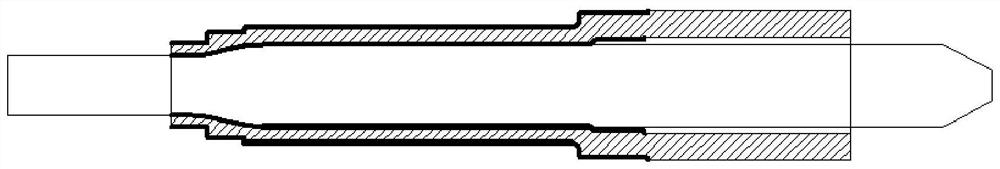
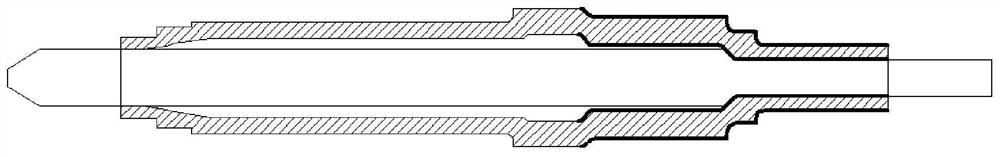
[0032] Such as Figure 1 to Figure 6 , the embodiment of the present invention discloses a lightweight motor shaft forming method, which includes the following steps:

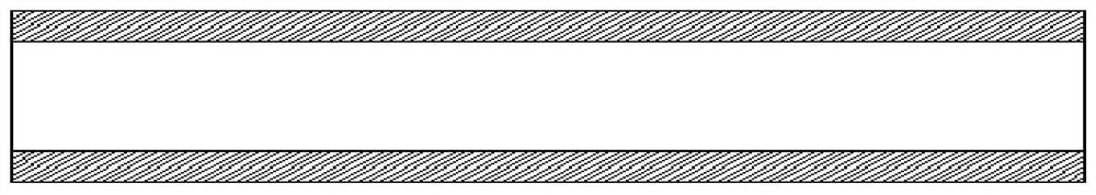
[0033] 1) Preparation of materials: prepare steel pipe materials, seamless steel pipes of appropriate size, preferably alloy structural steel, preferably 25CrMo4, with a hardness of HB210~212;

[0034] Cut the material according to the process requirements to obtain the required le...


PUM


Abstract

The present invention proposes a lightweight motor shaft forming method, comprising steps: 1), material preparation: material preparation of pipe material, first swaging die, second swaging die, first mandrel and second mandrel; 2) 1. Clamping in the first process: complete the clamping of the pipe material, the first swaging die and the first mandrel on the swaging machine; 3), the first process swaging: forming the pre-forged surface of the inner and outer surfaces of the bearing end of the hollow motor shaft; 4. ), the second process of clamping: complete the clamping of the pipe material, the second swaging die and the second mandrel on the swaging machine; 5), the second process of swaging: forming the inner and outer surfaces of the spline end of the hollow motor shaft to pre-satin ; 6), turning the end face of the motor shaft bearing, the end face of the spline and the outer circle; 7) the processing of the spline end. The light-weight motor shaft forming method disclosed in the present invention is formed by swaging twice through the tube material, without processing the inner hole of the motor shaft, so that the motor shaft can be hollowed out and lightened, the utilization rate of materials can be improved, and the motor shaft can be guaranteed. High precision on the inner and outer surfaces of the shaft.

Description

technical field [0001] The invention relates to the technical field of shaft parts processing, in particular to a lightweight motor shaft forming method. Background technique [0002] The power core of new energy vehicles is the drive motor, and the motor shaft mainly plays the role of fixing the rotor iron core and transmitting torque, so as to realize the mutual conversion between electric energy and mechanical energy; and connect the output shaft of the reducer and differential to control It is a key component that determines the driving performance and running stability of the car. Because the bearing moment of the motor shaft is very large, reaching 200-350N meters, the diameter of the motor shaft is relatively large. In the existing structure, it is usually increased to φ50-80mm, but the increase in diameter also increases the weight of the shaft accordingly. Its power transmission and rotation have great adverse effects, and its own weight needs to be reduced; in the...

Claims


Application Information

Patent Timeline
Patent Type & Authority Patents(China)
IPC IPC(8): B23P15/00H02K15/02H02K15/00
CPCB23P15/00H02K15/00H02K15/02
Inventor 汪朝晖徐文侠程自强高全杰武囡囡
Owner WUHAN UNIV OF SCI & TECH
Why Eureka
Try Eureka