An automatic disassembly and assembly line for hydraulic supports

A hydraulic support and sliding installation technology, applied in assembly machines, metal processing equipment, metal processing and other directions, can solve the problems of limited number of vehicles, high safety, hidden dangers, etc., to ensure assembly accuracy, improve production efficiency, and avoid extrusion deformation. Effect

Active Publication Date: 2020-11-17
ZHENGZHOU SUDA COAL MACHINERY SERVICE CO LTD
View PDF6 Cites 0 Cited by
  • Summary
  • Abstract
  • Description
  • Claims
  • Application Information

AI Technical Summary

Problems solved by technology

The mine pressure of the mining face acts on the hydraulic support in the form of external load. The hydraulic support plays a great role in the stability of the fully mechanized mining face. However, after a long period of use, the hydraulic support needs to be repaired or disassembled. However, the internal structure of the hydraulic support is complex, with angled mechanical structures and hydraulic cylinders. Part of the structure is designed to withstand pressure, and its own mass is relatively large. Lifting equipment is required for lifting during the disassembly process. In the prior art, most The disassembled parts are hoisted and placed by cranes and cranes. However, due to the limitation of the interior space of the workshop, the number of cranes is limited during operation, resulting in low disassembly and assembly efficiency of hydraulic supports. In the process of placing disassembled parts, Since the mounting surface of the workpiece is inconsistent with the load-bearing surface, it is necessary to manually turn the workpiece to avoid extrusion damage to the workpiece. Due to the large mass of the workpiece, there is a greater safety hazard when manually turning it over, which is not conducive to safe production.

Method used


Image

  • An automatic disassembly and assembly line for hydraulic supports
  • An automatic disassembly and assembly line for hydraulic supports
  • An automatic disassembly and assembly line for hydraulic supports

Examples


Embodiment Construction

[0021] The following will clearly and completely describe the technical solutions in the embodiments of the present invention with reference to the accompanying drawings in the embodiments of the present invention. Obviously, the described embodiments are only some of the embodiments of the present invention, not all of them. Based on the embodiments of the present invention, all other embodiments obtained by persons of ordinary skill in the art without making creative efforts belong to the protection scope of the present invention.

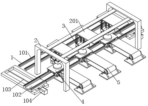
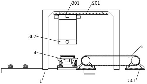
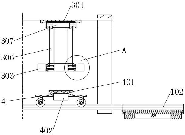
[0022] see Figure 1-6 , the present invention provides a technical solution: an automatic disassembly and assembly line for hydraulic supports, including a ring-shaped ground track 1, a track trolley 4 is installed inside the ground track 1, and a top fixing frame 2 is fixedly installed above the ground track 1, and the top fixing frame 2. The top rail 201 is fixed horizontally inside. The length direction of the top rail 201 is perpendicular to...


PUM


Abstract

The invention discloses an automatic assembling and disassembling line for a hydraulic support. The automatic assembling and disassembling line comprises a ring-shaped ground track. A track trolley isinstalled in the ground track in a matched manner. A top fixing frame is fixedly arranged above the ground track. A top track is horizontally and fixedly arranged in the top fixing frame. The lengthdirection of the top track is perpendicular to the ground track. An assembling and disassembling mechanism is installed in the top track in a sliding manner. The assembling and disassembling mechanismcomprises a hoisting frame which can move up and down. Two assembling clamp heads capable of telescoping are symmetrically arranged in the hoisting frame and can rotate coaxially. A conveying mechanism is arranged at the position, corresponding to the top track, of the side edge of the ground track. According to the automatic assembling and disassembling line for the hydraulic support, the assembly line production mode is adopted, a specific part is assembled and disassembled in a specific place, the production efficiency is improved, workpieces can be turned over automatically, potential safety hazards are eliminated, and safety production is benefitted.

Description

technical field [0001] The invention relates to the technical field of a hydraulic support disassembly line, in particular to an automatic hydraulic support disassembly line. Background technique [0002] The hydraulic support is a mechanical component used to prevent and control the mine pressure in the coal mining face. The mine pressure of the mining face acts on the hydraulic support in the form of external load. The hydraulic support plays a great role in the stability of the fully mechanized mining face. However, after a long period of use, the hydraulic support needs to be repaired or disassembled. However, the internal structure of the hydraulic support is complex, with angled mechanical structures and hydraulic cylinders. Part of the structure is designed to withstand pressure, and its own mass is relatively large. Lifting equipment is required for lifting during the disassembly process. In the prior art, most The disassembled parts are hoisted and placed by cranes...

Claims


Application Information

Patent Timeline
Patent Type & Authority Patents(China)
IPC IPC(8): B23P19/00B23P21/00
CPCB23P19/00B23P21/004
Inventor 黄泉清刘润平栗靖董博张芳卫许伟李小勇李银辉李攀攀姜红刘玉亮邵玉娥
Owner ZHENGZHOU SUDA COAL MACHINERY SERVICE CO LTD
Why Eureka
Try Eureka