Centrifugal pump shell processing jig

A centrifugal pump and casing technology, applied in the field of centrifugal pump production, can solve the problems of centrifugal pump casing fixtures such as single function, insufficient practicability, and poor operation coordination effect, and achieve compact structure, convenient processing operation, and smooth operation Effect

Active Publication Date: 2021-07-30
哈尔滨凯泉泵业有限公司
View PDF8 Cites 0 Cited by
  • Summary
  • Abstract
  • Description
  • Claims
  • Application Information

AI Technical Summary

Problems solved by technology

[0004] 1. The fixture of the centrifugal pump casing has a single function. Generally, it only has the function of clamping and positioning, and requires a pump body with multiple processing surfaces perpendicular to the same reference plane. The practicability is not wide enough.
[0005] 2. The centrifugal pump casing fixture is equipped with a multi-stage angle adjustment mechanism. The secondary angle adjustment mechanism requires additional equipment to adjust the angle of the pump body. The space utilization rate is low, and the operation of each structure is poor.

Method used


Image

  • Centrifugal pump shell processing jig
  • Centrifugal pump shell processing jig
  • Centrifugal pump shell processing jig

Examples


Embodiment 1

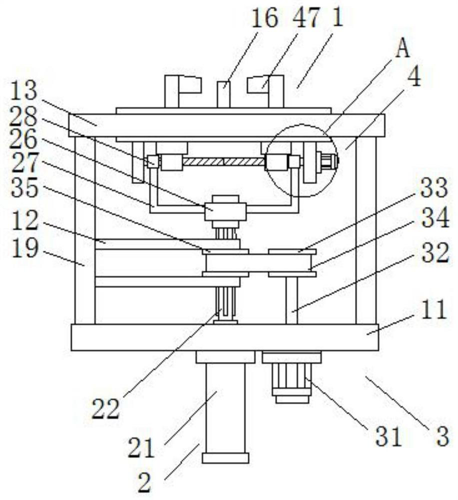
[0025] Example 1: Such as Figure 1-6 As shown, the specific embodiment employed the following technical solution: a centrifugal pump housing processing clamp, including a fixed frame 1, a compression mechanism 2, a rotating mechanism 3, and a clamping mechanism 4, and a fixed frame 1 is mounted. The rotating mechanism 3 and the clamping mechanism 4, the rotating mechanism 3 is connected to the compression mechanism 2, and the compression mechanism 2 is connected to the clamping mechanism 4.

[0026] Wherein, the fixed frame 1 includes a bottom plate 11, a support plate 12, a fixing plate 13, a slide groove 14, a screw hole 15, a positioning rod 16, a rectangular frame 17, a rotating tray 18, and a connecting plate 19, and a fixed plate 13 is provided. Two connecting plates 19 are fixed between the bottom plate 11 and the fixing plate 13, where two support plates 12 are fixed to the side walls of the connecting plate 19, and the middle of the fixing plate 13 is embedded with a rota...

Embodiment 2

[0035] Example 2: The press-fitting clamp 47 end in the first embodiment mounts the centrifugal pump grip model, and is activated by the two half-model settings, and the secondary rotating shaft 42 is activated. Turning, the external thread 44 is threaded with the threaded sleeve 45, and the two press-fitting hooks 47 are close to each other, and the two half modes are close to each other, and the two semi-molds are sandwiched on both sides of the centrifugal pump. On, thereby effectively positioning the centrifugal pump, can be treated more comprehensively, and the outer wall of the centrifugal pump is more comprehensive, and the friction coaxial is connected between the secondary motor 41 output shaft and the secondary shaft 42 can effectively avoid the clamping action overload. , The case where the second motor 41 or external thread 44 is damaged.


PUM


Abstract

The invention discloses a jig for processing a centrifugal pump shell, which comprises a fixed frame, a pressing mechanism, a rotating mechanism and a clamping mechanism. Connection, the pressing mechanism is connected with the clamping mechanism, the fixed frame includes the bottom plate, the supporting plate, the fixing plate, the chute, the threaded hole, the positioning rod, the rectangular frame, the rotating tray and the connecting plate, the fixture of the centrifugal pump shell, the pressing mechanism , the rotation mechanism and the clamping mechanism are combined in turn, the setting of the connecting sleeve can meet the rotation requirements of the second rotating shaft, the setting of the limit slide bar and the linear groove can meet the sliding requirements of the collar when the central rotating shaft rotates, so that Each mechanism can operate independently, and each operating mechanism does not need to load the weight of other driving equipment. The coordination effect of each mechanism is good, and the space utilization rate is high. The pump body is fixed by fixing the flange, and the specific clamping model is avoided to effectively fix the pump body. disadvantages.

Description

Technical field: [0001] The present invention belongs to a clamping device, and more particularly to a centrifugal pump housing processing fixture, which belongs to the field of centrifugal pump production. Background technique: [0002] The structure of the centrifugal pump is complex. The castings account for more than 80%, mainly cast iron parts, cast steel parts and cast stainless steel parts, less shaft parts, mainly high quality carbon steel, chrome steel or stainless steel, centrifugal pump parts processing Because it has a hydraulic flow path, it is necessary to find the correct position of the flow path in consideration of the positioning equipment, and avoid assembly, which causes the spline and impeller flow path to be skewed, mishanded, gap is not even touched, affecting the product Quality, in order to ensure that parts manufacturing accuracy, need to design the corresponding tooling, and arrange the process flow reasonably. [0003] In the comparative document of Pa...

Claims


Application Information

Patent Timeline
Patent Type & Authority Patents(China)
IPC IPC(8): B23Q3/00B23Q3/08B23Q7/00
CPCB23Q3/00B23Q3/062B23Q3/08B23Q7/00B23Q2703/04
Inventor 孟萍
Owner 哈尔滨凯泉泵业有限公司
Why Eureka
Try Eureka