
Construction method of foundation pit supporting structure of prefabricated reinforced concrete combined support

A foundation pit support and prefabricated assembly technology, which is applied in infrastructure engineering, excavation, construction, etc., can solve the problems of increasing the cost of construction waste treatment, the inability to effectively recycle steel beams, and the long time of concrete, etc., to achieve high rigidity, The effect of light weight and fast construction speed

Active Publication Date: 2020-05-29
TIANJIN UNIV
View PDF13 Cites 0 Cited by
  • Summary
  • Abstract
  • Description
  • Claims
  • Application Information

AI Technical Summary

Problems solved by technology

However, steel-concrete composite beams are used as supporting members, and like reinforced concrete supporting members, it takes a long time to pour concrete on site
In addition, when the support is removed after the foundation pit support project is completed, not only will there be a lot of vibration and noise, but the demolition period will be relatively long
From the perspective of material recycling, in the composite beam support, since the steel beam and the cast-in-place reinforced concrete part are integrated by welding studs, the steel beam cannot be effectively recycled when it is dismantled, and it can only be discarded, which increases the cost of construction waste disposal

Method used

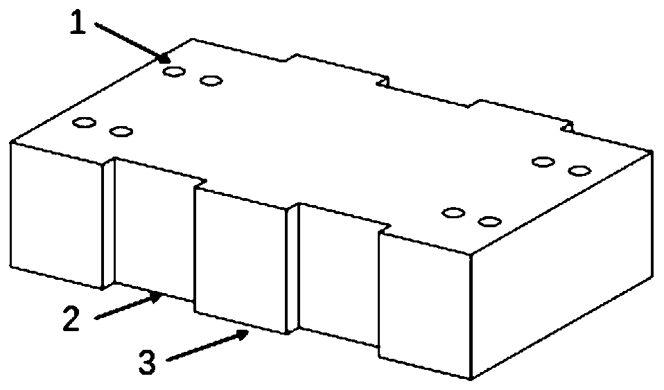
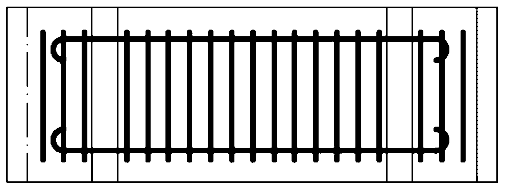
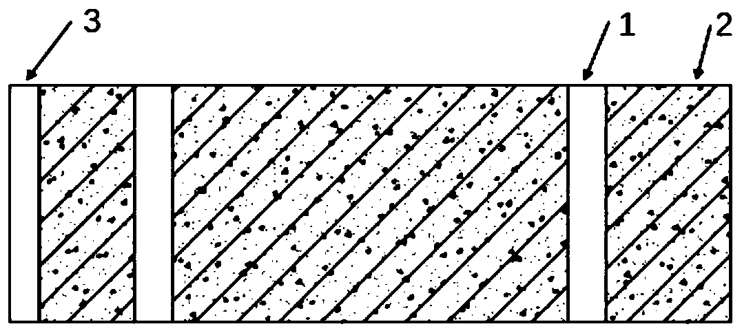

Image

  • Construction method of foundation pit supporting structure of prefabricated reinforced concrete combined support
  • Construction method of foundation pit supporting structure of prefabricated reinforced concrete combined support
  • Construction method of foundation pit supporting structure of prefabricated reinforced concrete combined support

Examples


Embodiment Construction

[0041] The present invention will be further elaborated below by specific examples.

[0042] A foundation pit supporting method of a prefabricated assembled steel-concrete composite support as shown in the accompanying drawing, comprising the following steps:

[0043]Step 1, referring to Fig. 10(a), a circle of steel purlins 10 is set along the surrounding wall of the foundation pit, and the front row of steel columns and the rear row of steel columns are respectively driven into the front and rear sides of the foundation pit along the vertical direction. Column 8, front steel column and rear steel column 8 respectively comprise a plurality of steel columns arranged at left and right intervals; The distance between them is 6-9m, and the distance between the two front and rear steel columns 8 corresponding to each other is 6-9m, so that the structure design is reasonable, the plane layout is reasonable, and the construction is convenient.

[0044] Step 2, welding a steel corbe...


PUM


Abstract

The invention discloses a foundation pit supporting method of a prefabricated reinforced concrete combined support. The method includes the following steps that a circle of steel enclosing purlins arearranged along an enclosure wall of a foundation pit, and steel stand columns are arranged on the front side and the rear side in the foundation pit; a steel corbel is welded to the outer wall of each steel stand column; a front steel waist beam and a rear steel waist beam are fixed to upper flange plates of the steel corbels of the steel stand columns through high-strength bolts; the front steelwaist beam and the rear steel waist beam are each provided with multiple sets of reinforced concrete combined supporting structures at intervals in a left-right manner; and a hydraulic jack is placedbetween a vertical plate of each piece of angle iron and the corresponding steel enclosing purlin, and pressure is uniformly loaded on prefabricated steel beams and prefabricated concrete plates by the hydraulic jacks through the angle iron. The combined support is formed by combining the prefabricated concrete plates and the steel beams and is convenient to install and detach, high in construction speed and capable of being repeatedly used, the supporting effect can be achieved by exerting pre-pressure through the jacks, and the magnitude of the supporting force can be regulated.

Description

technical field [0001] The invention relates to a foundation pit support structure and a construction method thereof, in particular to a prefabricated assembled steel-concrete composite support structure and a construction method thereof for foundation pit support. Background technique [0002] Foundation pit support is a temporary support, reinforcement, protection and groundwater control measure for the foundation pit to protect the construction of the main underground structure and the surrounding environment of the foundation pit. [0003] Commonly used deep foundation pit support structures include cantilever support, soil nail wall support, internal support support, anchor support, cement-soil gravity support wall, underground diaphragm wall, and combined support. The cantilever support has the disadvantages of poor water-stopping ability, long construction period, sensitivity to excavation depth, and easy to produce large deformation. Soil nail wall support has disad...

Claims


Application Information

Patent Timeline
IPC IPC(8): E02D17/04
CPCE02D17/04
Inventor 罗云标王敬贺张稳军刘会州
Owner TIANJIN UNIV
Learn More