Milling machine fixture and clamping method for air fuel radiator core assembly

A milling machine fixture and radiator technology, which is applied in the field of mechanical processing, can solve the problems of non-adjustable auxiliary support force, deformation of component clamping and processing, and lack of auxiliary support points, etc., to achieve convenient adjustment and coordination of limit positions, and convenient positioning and clamping operations , The effect of convenient leveling process

Active Publication Date: 2022-07-12
GUIZHOU YONGHONG AVIATION MACHINERY
View PDF0 Cites 0 Cited by
  • Summary
  • Abstract
  • Description
  • Claims
  • Application Information

AI Technical Summary

Problems solved by technology

[0003] for Figure 5 For the two positions to be milled of the core assembly of the hollow air fuel radiator, the existing clamping method is to use an assembly fixture, use the flange connection plate C as the positioning surface to stick to the fixture, and then apply a vertical force from the end surface where the waist groove is located. The pressure of the flange surface compresses the core assembly of the air-fuel radiator. This traditional alignment, adjustment, positioning and clamping method is not only difficult to align and clamp (when the flange connection plate C is used as the positioning surface to be close to the fixture, it cannot be aligned with the milling machine. platform rotation, lack of auxiliary support points, and the size of the auxiliary support force cannot be adjusted), the product quality is not good, and it is easy to cause deformation of the component clamping process (applying pressure from one end of the waist-shaped groove will easily cause the end surface where the waist-shaped groove is located to be damaged. In addition, due to the lack of compression structure of the flange connection plate, when the waist-shaped groove and the sag-reducing plane are processed, the flange surface of the flange connection plate is no longer flat), causing the product to be scrapped. In order to meet the actual needs of production, it is urgent to design A set of milling machine fixtures and corresponding clamping methods for air-fuel radiator core assemblies

Method used


Image

  • Milling machine fixture and clamping method for air fuel radiator core assembly
  • Milling machine fixture and clamping method for air fuel radiator core assembly
  • Milling machine fixture and clamping method for air fuel radiator core assembly

Examples


Embodiment Construction

[0053] The embodiments of the present invention will be further described below with reference to the accompanying drawings, but the protection scope of the claims of the present invention is not limited to the contents listed in this embodiment.

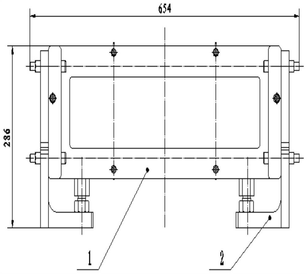
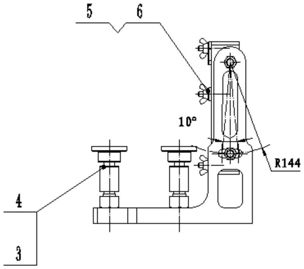
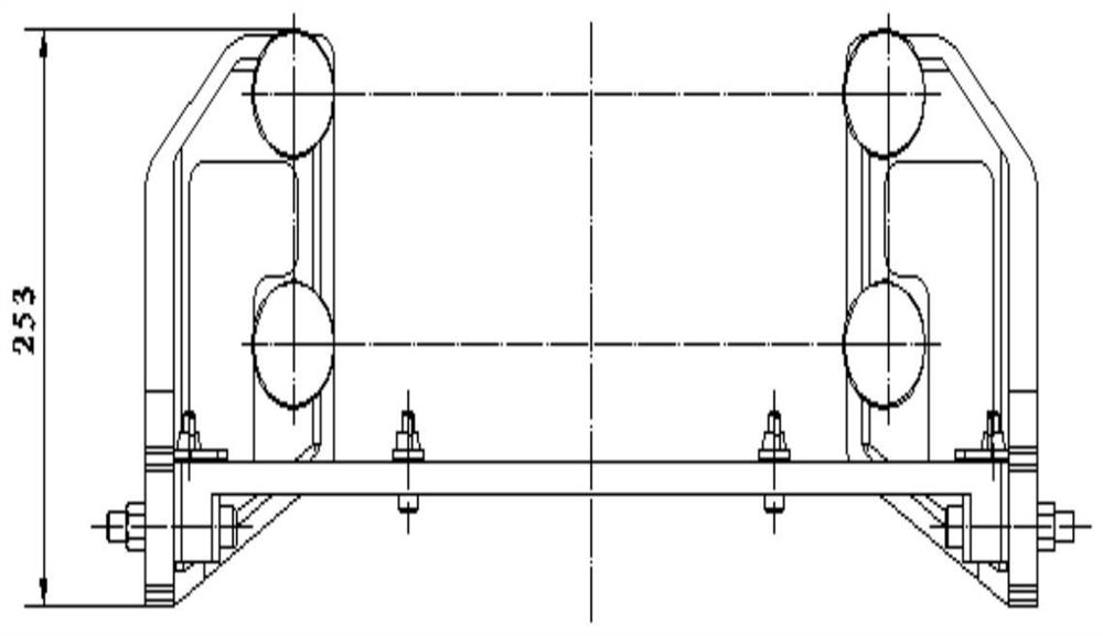
[0054] In this embodiment, the milling machine fixture for the air-fuel radiator core assembly includes: a flange positioning plate 1, a mounting support 2, an adjusting screw 3, a positioning block 4, a pressing plate 5, a connection locking member 6, and the like. See each view of the milling machine fixture for the air fuel radiator core assembly Figure 1 to Figure 4 shown; the structure diagram of the air fuel radiator core assembly is shown in Figure 5 , the schematic diagram of the product with the core component installed on the milling machine fixture of the air fuel radiator core component is shown in Image 6 .

[0055] The functions and structural characteristics of each component in the milling machine fixture of the ...


PUM


Abstract

The invention provides a milling machine fixture and a clamping method for an air fuel radiator core assembly. The milling machine fixture includes a flange positioning plate, an installation support, an adjusting screw, a positioning block, a pressing plate and a connection locking piece. The flange positioning plate can be rotated to adjust the angle relative to the installation support. The adjusting screw and the positioning block can be raised and lowered to form the support and limit for the air fuel radiator core assembly. And the connection locking piece is fixed on the flange positioning plate. The invention facilitates adjustment and positioning processing, improves work efficiency, ensures product performance consistency, and improves product appearance quality at the same time.

Description

technical field [0001] The invention relates to a fixture for mounting a milling machine and a clamping method using the fixture, in particular to a fixture and a clamping method suitable for an air-fuel radiator core assembly, belonging to the technical field of machining. Background technique [0002] As a part of the aircraft environmental control system, the air fuel radiator is an important product component. The consistency of its manufacturing quality is particularly important. The product weight requirements are relatively strict, especially the appearance quality of the product is more important. . like Figure 5 Shown is a three-dimensional view of the air-fuel radiator core assembly. The air-fuel radiator core assembly is a cavity cube-shaped shell part. One end face of the shell part has a ring of flange connection disk C. The flange connection Plate C needs to ensure that the flange surface is flat. During subsequent installation and processing, the flange surf...

Claims


Application Information

Patent Timeline
Patent Type & Authority Patents(China)
IPC IPC(8): B23Q3/06
CPCB23Q3/062
Inventor 孙德明黄晨葛光荣
Owner GUIZHOU YONGHONG AVIATION MACHINERY
Why Eureka
Try Eureka