Pushing perforating device used for furniture wood board machining

A technology of punching device and wood board, which is applied to fixed drilling machines and other directions, can solve the problem of manual pushing for wood board punching and conveying, and achieve the effect of improving punching efficiency and being easy to use.

Inactive Publication Date: 2020-03-24
李可娟
View PDF0 Cites 3 Cited by
  • Summary
  • Abstract
  • Description
  • Claims
  • Application Information

AI Technical Summary

Problems solved by technology

[0004] The purpose of the present invention is to provide a pushing and punching device for furniture wood processing to solve the problem that manual pushing is required for the punching and conveying of wood boards

Method used


Image

  • Pushing perforating device used for furniture wood board machining
  • Pushing perforating device used for furniture wood board machining
  • Pushing perforating device used for furniture wood board machining

Examples


Embodiment 1

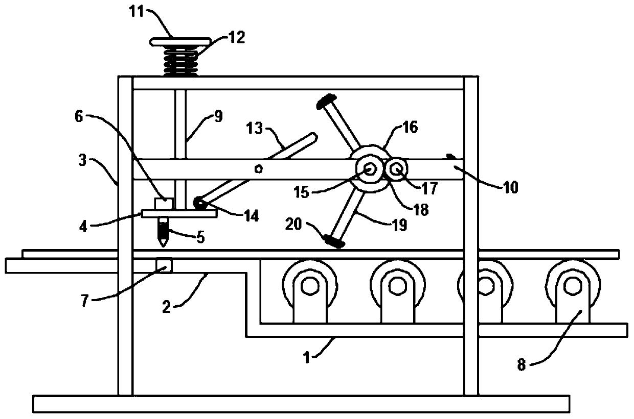
[0022] see Figure 1~3 , in an embodiment of the present invention, a pushing and punching device for furniture board processing includes a base substrate, an installation outer frame 3 arranged on the base substrate, and a conveying platform for conveying wooden boards, and the conveying platform includes horizontal state of the first pallet 1 and the second pallet 2, the first pallet 1 and the second pallet 2 are installed on the installation frame 3, the first pallet 1 and the second pallet 2 are close to the end Connected as a whole to form a Z-shaped structure, the first pallet 1 is provided with a plurality of equidistantly distributed idlers 8, and the arc top of the idler 8 is at the same height as the upper end surface of the second pallet 2. The middle part of the outer frame 3 is provided with a horizontal frame 10 and a drilling assembly and a pushing assembly are installed on the horizontal frame 10. The drilling assembly includes a mounting plate 4 and a drilling...

Embodiment 2

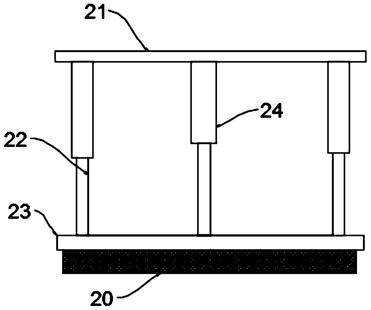
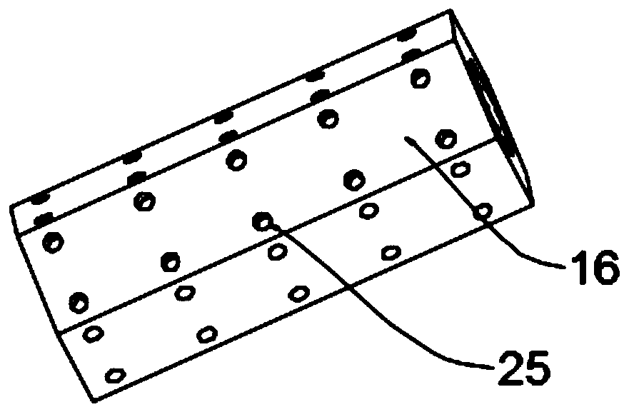
[0026] The difference between the embodiment of the present invention and embodiment 1 is that the push rod 19 includes a push rod 23 and a connecting cross bar 21 connected to the outer wall of the installation roller 16, and the two ends of the connecting cross rod 21 are connected by telescopic rods. 22 is connected to the two ends of the push rod 23, the connecting rod 21 is also provided with an adjustment cylinder 24 and the telescopic end of the adjustment cylinder 24 is fixed on the outer wall of the push rod 23, and the rubber spring pad 20 is installed on the push rod 23 Above, the length of the push rod 19 can be adjusted by adjusting the expansion and contraction of the cylinder 24, and then the time when the rubber elastic pad 20 is in contact with the wood board can be adjusted to adjust the distance that the board is pushed, and then the distance between the holes can be adjusted, which is convenient and quick. The connecting cross bar 21 is detachably connected ...


PUM


Abstract

The invention discloses a pushing perforating device used for furniture wood board machining, and relates to the technical field of wood board machining. The pushing perforating device mainly aims atsolving the problem that wood board perforating conveying needs manual pushing. The perforating device comprises a base basal plate, an installation outer frame arranged on the base basal plate and aconveying table used for wood board conveying. The conveying table comprises a first supporting plate and a second supporting plate which are both in a horizontal state. Multiple carrier rollers distributed at equal intervals are arranged on the first supporting plate. A transverse frame is arranged on the middle portion of the installation outer frame, and a drilling assembly and a pushing assembly are installed on the transverse frame. A rotating pushing and pressing rod is further arranged on the transverse frame, the middle portion of the rotating pushing and pressing rod is hinged to thetransverse frame through a hinge pin, and one end of the rotating pushing and pressing rod is located on the upper side of an installation plate. The device does not need manual control and operationand can continuously conduct perforating, and the perforating efficiency can be effectively improved; and meanwhile, due to the fact that the distance by which a wood board is pushed by push rod pieces to move each time is the same, the perforating gaps are equal, and use is facilitated.

Description

technical field [0001] The invention relates to the technical field of wood board processing, in particular to a pushing and punching device for furniture wood board processing. Background technique [0002] Furniture refers to the category of utensils and facilities necessary for human beings to maintain normal life, engage in production practice and carry out social activities. Furniture also follows the footsteps of the times and continues to develop and innovate. Up to now, there are many categories, different materials, complete varieties, and different uses. All the materials used in wooden furniture are basically wooden panels, including desktops, wardrobe doors, side panels, etc. Made of wood, wooden furniture has high requirements on craftsmanship and materials. The selection of wood materials, drying, finger joints, and seams are very strict. If any process is not strictly controlled, cracks and loose joints will occur, and the entire furniture will be deformed an...

Claims


Application Information

Patent Timeline
Patent Type & Authority Applications(China)
IPC IPC(8): B27C3/02
CPCB27C3/02
Inventor 李可娟
Owner 李可娟
Why Eureka
Try Eureka