
Integrally-formed winding elbow assembling die

A mold and integrated technology, which is applied to household appliances, other household appliances, household components, etc., can solve the problems of single mold processing model, high processing cost, and low product life, so as to reduce production cost, increase operating space, and improve production efficiency. high efficiency effect

Pending Publication Date: 2020-03-24
李世昌
View PDF0 Cites 2 Cited by
  • Summary
  • Abstract
  • Description
  • Claims
  • Application Information

AI Technical Summary

Problems solved by technology

[0003] The existing technology has the following disadvantages: the original FRP elbow processing mold is designed with a metal structure, and it is a vertical split structure, which is heavy and requires manual materials to be bonded and pasted. Pull to complete the demoulding; because the manual processing of the FRP elbow after demoulding is extremely rough, it needs to be polished to meet the requirements of the finished product. The processing cost is high, time-consuming and laborious, and the wall thickness of the finished product is irregular and non-standard, so it cannot be used in any site; The original mold processing model is single, which cannot be applied to the processing of elbows with other angles in the market; the finished product of elbow and socket cannot be completed in one piece, and the two parts need to be processed separately before bonding, and the life of the finished product after bonding is low , and the production cost is high and the standard is low

Method used


Image

  • Integrally-formed winding elbow assembling die
  • Integrally-formed winding elbow assembling die
  • Integrally-formed winding elbow assembling die

Examples


Embodiment Construction

[0027] The following will clearly and completely describe the technical solutions in the embodiments of the present invention with reference to the accompanying drawings in the embodiments of the present invention. Obviously, the described embodiments are only some, not all, embodiments of the present invention. Based on the embodiments of the present invention, all other embodiments obtained by persons of ordinary skill in the art without making creative efforts belong to the protection scope of the present invention.

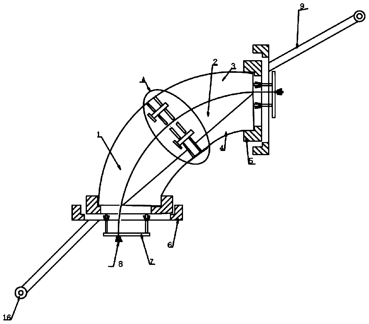
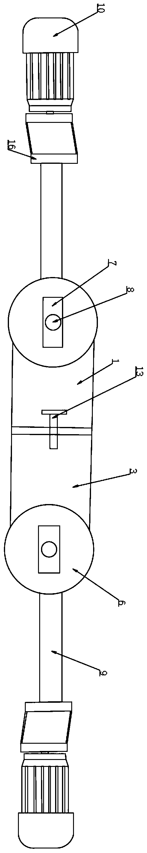
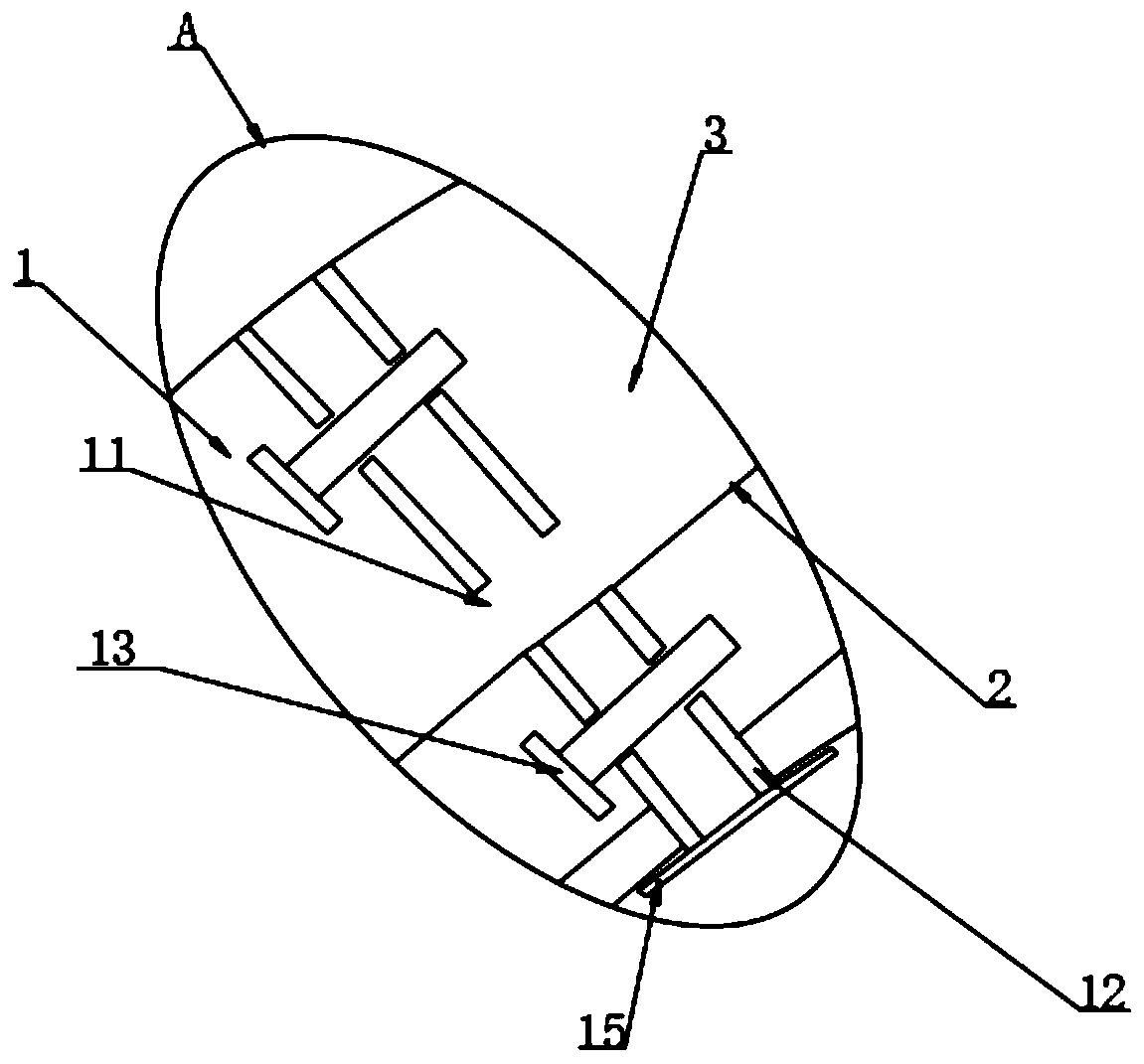
[0028] The present invention provides an integrally formed winding elbow assembly mold as shown in Fig. The inside of the mold 3 is provided with a steel wire rope 2, the inside of both ends of the upper mold 1 and the lower mold 3 are provided with assembly blocks 4, and the connection between the upper mold 1 and the lower mold 3 is provided with a support plate 12, The tops of the two supporting plates 12 are correspondingly provided with positioning holes ...


PUM


Abstract

The invention discloses an integrally-formed winding elbow assembling die comprising an upper die. A lower die is arranged at the bottom of the upper die. A steel wire rope is arranged in the upper die and the lower die in a penetrating manner. Splicing blocks are arranged on the inner sides of the two ends of the upper die and the lower die, supporting plates are arranged at the connecting positions of the upper die and the lower die, positioning holes are correspondingly formed in the top of the two supporting plates, positioning pins are arranged in the two positioning holes in a penetrating mode, and crescent holes are formed in the corresponding positions of the bottom of the two positioning holes. The nuts at the two ends of the steel wire rope are unscrewed firstly, the sealing plates and the socket sleeves are disassembled, then the splicing blocks on the inner sides of the two ends of the die are disassembled, and finally a finished product formed through winding is pulled toone end and demolding is realized. The splicing blocks are additionally arranged to facilitate demolding of the finished product, the socket is slightly wider than the elbow and thus disassembling ismore convenient by disassembling the splicing blocks.

Description

technical field [0001] The invention relates to the technical field of processing moulds, more specifically, the utility model relates to an integrally formed winding elbow assembly mold. Background technique [0002] In the pipeline system, the elbow is a pipe fitting that changes the direction of the pipeline. According to the angle, there are three most commonly used types: 45° and 90° 180°. In addition, according to engineering needs, other abnormal angle elbows such as 60° are also included. The materials of elbows include cast iron, stainless steel, alloy steel, malleable cast iron, carbon steel, non-ferrous metals and plastics, etc., and the connection methods with pipes are: direct welding (the most commonly used method) flange connection, hot-melt connection, electric fusion connection, Threaded connection and socket connection, etc., according to the production process can be divided into: welding elbow, stamping elbow, push elbow, casting elbow, butt welding elbow...

Claims


Application Information

Patent Timeline
IPC IPC(8): B29C70/54B29C70/30B29C33/30B29L31/24
CPCB29C33/30B29C33/305B29C70/30B29C70/54B29L2031/243
Inventor 李世昌
Owner 李世昌
Features
  • Generate Ideas
  • Intellectual Property
  • Life Sciences
  • Materials
  • Tech Scout
  • Unparalleled Data Quality
  • Higher Quality Content
  • 60% Fewer Hallucinations
Learn More