Lock body and sliding door and window
A lock body and lock tongue technology, used in door/window fittings, building locks, windows/doors, etc., can solve the problems of easy first encounter, complex structure, affecting the closing of the door panel, etc., to achieve stable performance, large application environment, simple structure
- Summary
- Abstract
- Description
- Claims
- Application Information
AI Technical Summary
Problems solved by technology
Method used
Image

Examples
Embodiment 1
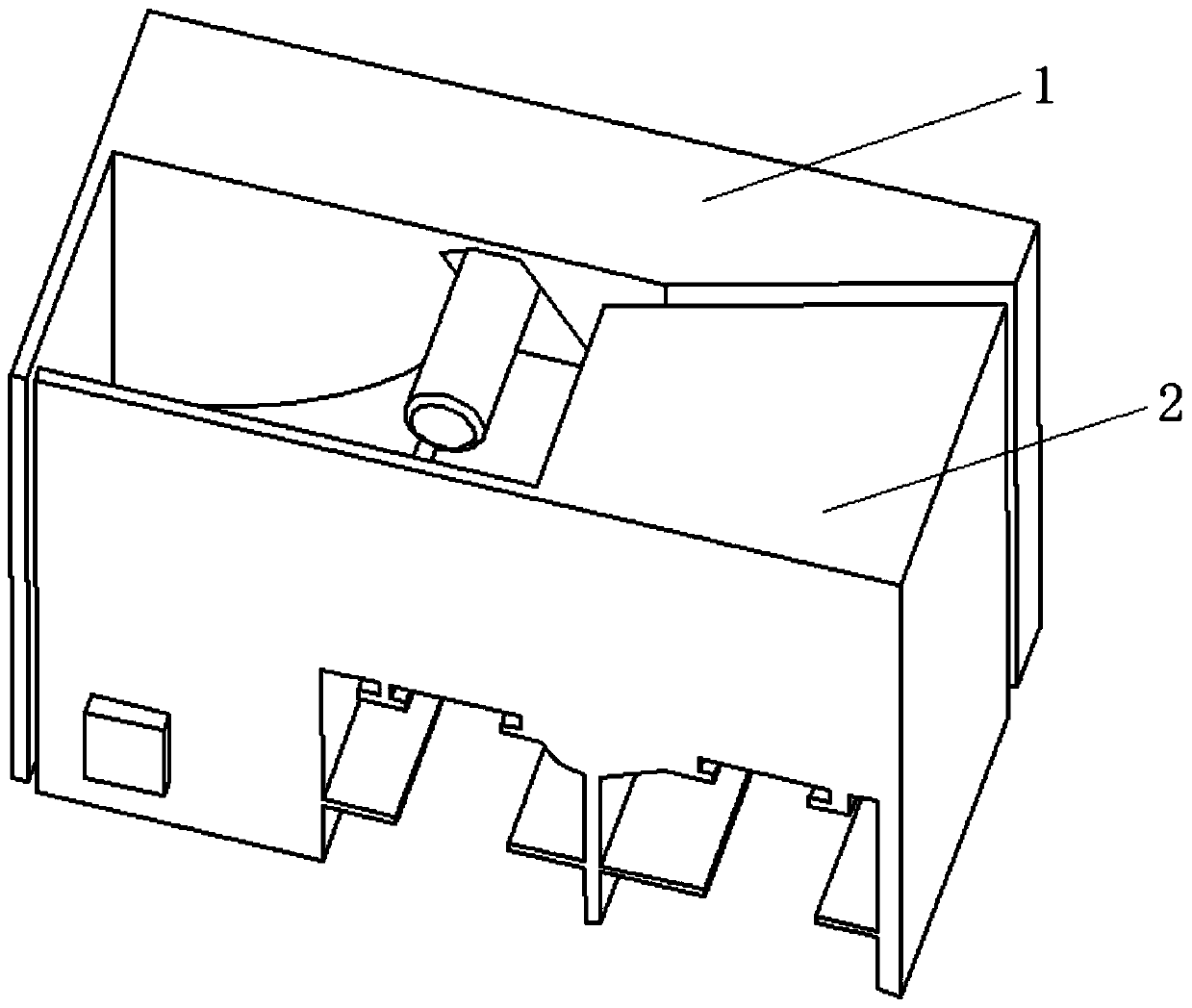
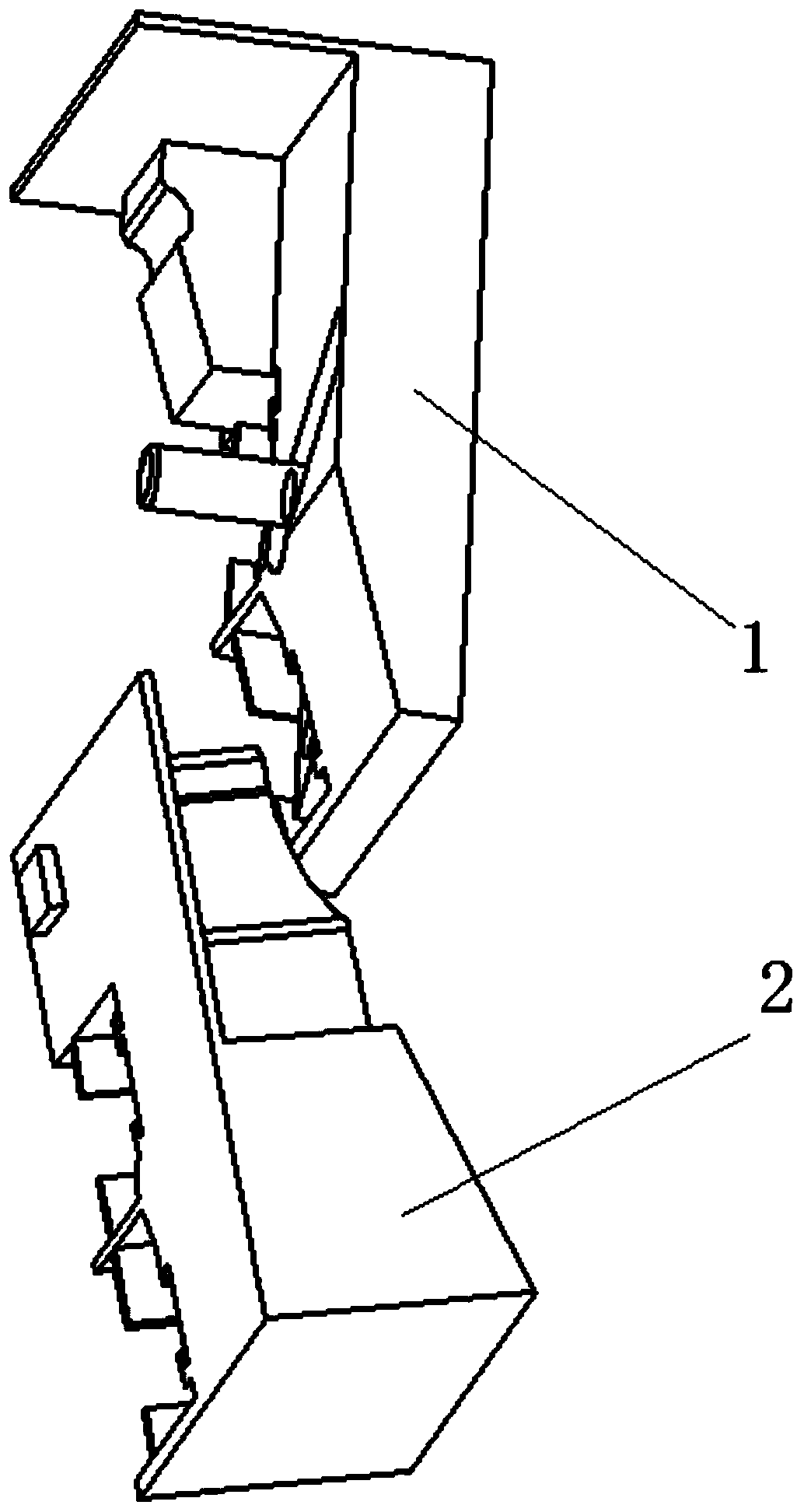
[0026] like figure 1 and figure 2 Shown is a schematic diagram of the overall structure and a schematic diagram of the matching structure of the lock body in Embodiment 1 of the present invention.
[0027] The side-opening sliding door and window comprises a door and window body (not shown in the figure), a first door panel cavity 15, and a second door panel cavity 16, and the door panel slides back and forth in the two door panel cavities. Wherein the first door panel cavity 15 and the second door panel cavity 16 are arranged on the first tap mechanism 1, and the first tap mechanism 1 can move together with the sliding track fixed on the door panel. In addition, the sliding track fixed on the door frame The track cannot be moved, and the end of the sliding track is provided with a second tap mechanism 2, and the second tap mechanism 2 is designed with a first door panel cavity 25, a second door panel cavity 26, a first door panel cavity 15 and a first door panel cavity 25,...
Embodiment 2
[0032] Figure 7 It is a schematic diagram of the first tapping mechanism of the lock body in Embodiment 2 of the present invention.
[0033] Figure 8 It is a schematic diagram (the other side) of the first tapping mechanism of the lock body in Embodiment 2 of the present invention.
[0034] Figure 9 It is a schematic diagram of the second tapping mechanism of the lock body in Embodiment 2 of the present invention.
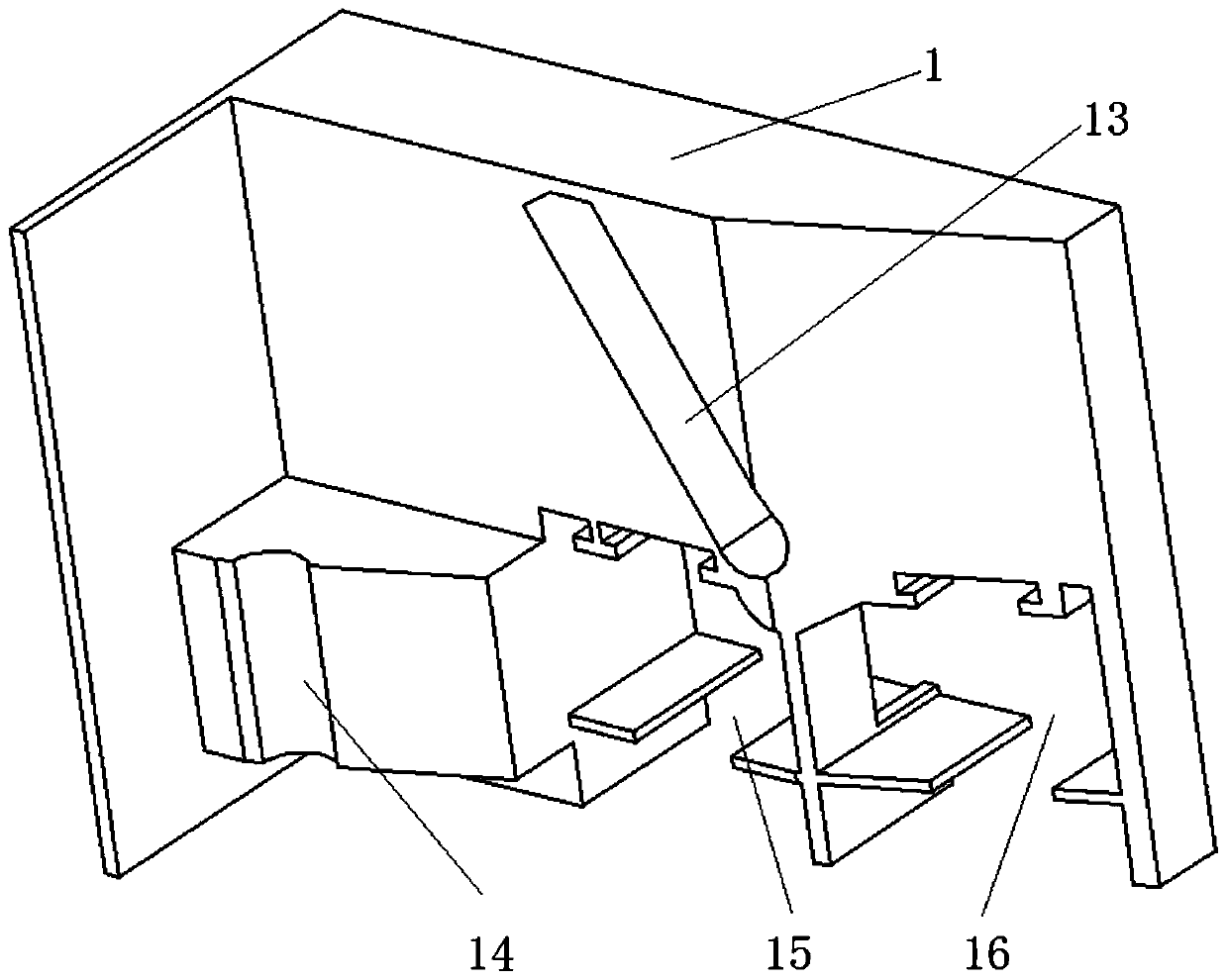
[0035] In the sliding door and window of the present embodiment, the first tap mechanism of the lock body only has the first door panel cavity 15, and there is no second door panel cavity 16. Correspondingly, only the first door panel cavity 25 is arranged in the second tap mechanism, and there is no The second door panel cavity 26 . The lock body of Embodiment 2 includes a first tap mechanism 1 and a second tap mechanism 2 matched with the first tap mechanism 1, and the first tap mechanism 1 includes a pole 11, a lock tongue 12 and a slideway 13 , the seco...
PUM
 Abstract
Description
Claims
Application Information
 - R&D
- Intellectual Property
- Life Sciences
- Materials
- Tech Scout
- Unparalleled Data Quality
- Higher Quality Content
- 60% Fewer Hallucinations
Browse by: Latest US Patents, China's latest patents, Technical Efficacy Thesaurus, Application Domain, Technology Topic, Popular Technical Reports.
© 2025 PatSnap. All rights reserved.Legal|Privacy policy|Modern Slavery Act Transparency Statement|Sitemap|About US| Contact US: help@patsnap.com