
Coal mine underground reservoir box type retaining dam

A technology for underground reservoirs and retaining dams, applied in mining equipment, water conservancy projects, mining equipment, etc., can solve the problems of poor water-stopping and anti-seepage effects, limited bending resistance, and limited effects, so as to avoid excessive local pressure , Enhanced bending resistance and anti-softening effect

Active Publication Date: 2021-01-08
CHINA UNIV OF MINING & TECH (BEIJING)
View PDF7 Cites 0 Cited by
  • Summary
  • Abstract
  • Description
  • Claims
  • Application Information

AI Technical Summary

Problems solved by technology

[0008] The applicant’s prior invention patent applications CN201910087850.2, CN201910086889.2 and CN201910087871.4 all disclose a coal mine underground reservoir retaining dam, which is located between the coal pillar dams on the left and right sides of the roadway and is used to isolate the underground reservoir and The roadway blocks the water source in the underground reservoir, but the main structure of the dam body adopts the I-shaped concrete structure dam body, and the left and right ends of the "I"-shaped upper flange, web and lower flange are embedded in the In the coal pillar dam, the upper wing plate is embedded in the surrounding rock of the roadway roof, and the lower wing plate is embedded in the surrounding rock of the roadway floor. The combined structure of the I-shaped wing and web is relatively complicated, and the effect of the upper and lower wings in solving local stress damage is limited. Not very good

Method used


Image

  • Coal mine underground reservoir box type retaining dam
  • Coal mine underground reservoir box type retaining dam
  • Coal mine underground reservoir box type retaining dam

Examples


Embodiment Construction

[0037] In order to make the purpose, technical solutions and advantages of the embodiments of the present invention more clear, the embodiments of the present invention will be further described in detail below in conjunction with the embodiments and the accompanying drawings. Here, the exemplary embodiments and descriptions of the present invention are used to explain the present invention, but not to limit the present invention.

[0038] In describing the present invention, it should be understood that the terms "upper", "lower", "front", "rear", "left", "right", "top", "bottom", "inner", " "Outside" and other indication orientations or positional relationships are based on the orientations or positional relationships shown in the drawings, which are only for the convenience of describing the present invention and simplifying the description, rather than indicating or implying that the referred device, component or structure must have a specific orientation, Construction or ...


PUM


Abstract

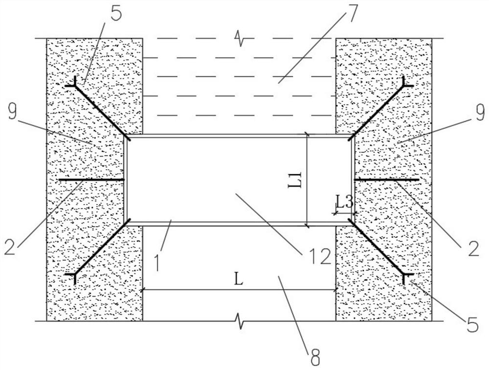
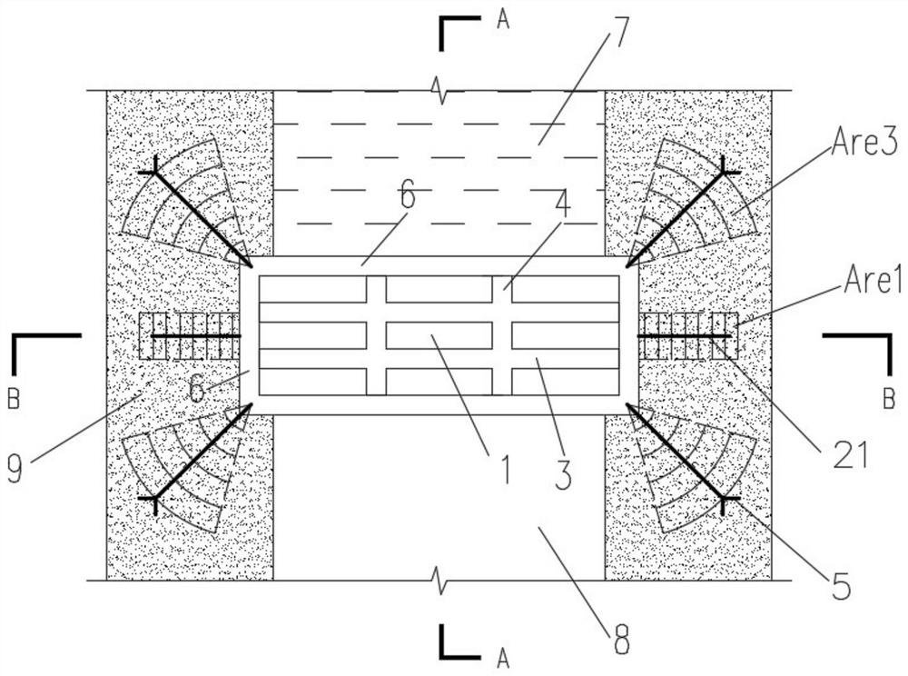
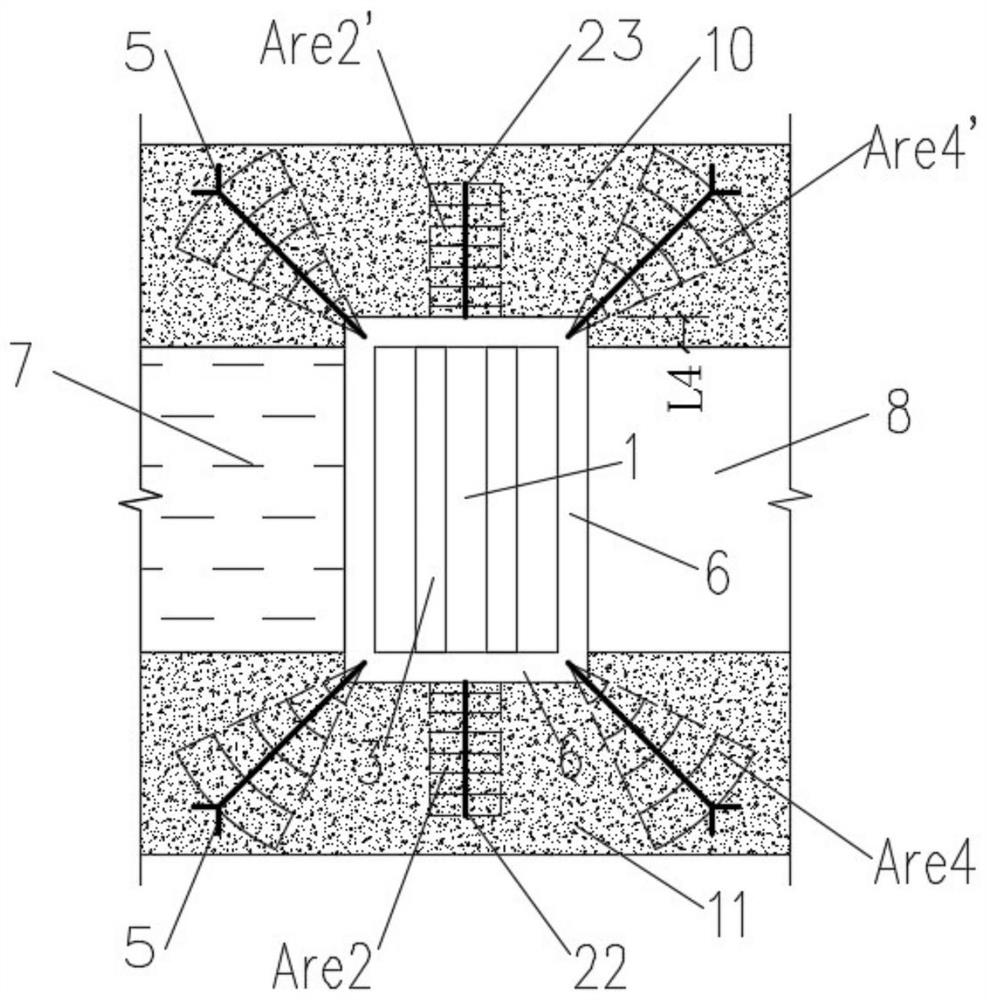
The invention discloses a box type water retaining dam for a coal mine underground reservoir. The box type water retaining dam is located between coal pillar dam bodies on the left side and the rightside of a roadway and used for isolating the underground reservoir and the roadway and blocking a water source in the underground reservoir. The box type water retaining dam comprises a main dam bodyand water retaining wings, wherein the main dam body is of a box type structure, the left side and the right side of the main dam body are embedded in the coal pillar dam bodies on the two sides, thetop of the main dam body is embedded in roadway roof surrounding rock, and the bottom of the main dam body is embedded in roadway bottom plate surrounding rock; and the water retaining wings compriseside wings, the side wings are connected with the left side and the right side of the main dam body and arranged along at least the whole height range of the main dam body, the side wings are embeddedinto the coal pillar dam bodies on the two sides to a certain depth, and thus side wing seepage prevention areas are formed. The box type water retaining dam can reduce crippling and water seepage caused by excessive local stress of the surrounding rock at the same time, adjusts differential settlement, prevents the surrounding rock from being softened due to water entering, and ensures the stability and safety of the dam bodies.

Description

technical field [0001] The invention relates to the intersecting fields of mining engineering and water conservancy engineering, in particular to a box-type retaining dam of underground reservoirs in coal mines. Background technique [0002] The construction of sluice gates and sluice walls is regulated in the "Coal Mine Safety Regulations" and "Coal Mine Water Prevention and Control Regulations", which are mainly based on the perspective of water prevention and control, without considering the long-term role of underground reservoir water storage; The construction of the dam body has been stipulated in more detail. Although there have been related studies on the construction of the retaining dam of the distributed underground reservoir in coal mines, the construction of the dam body of the surface reservoir and the construction of the retaining dam of the underground reservoir are obviously different. [0003] Comparing the dam body of the underground reservoir of the coal ...

Claims


Application Information

Patent Timeline
Patent Type & Authority Patents(China)
IPC IPC(8): E21F17/16E02B7/02
CPCE02B7/02E21F17/16
Inventor 孔祥松单仁亮张浩琛
Owner CHINA UNIV OF MINING & TECH (BEIJING)
Learn More