
Brake calliper of a disk brake for motor vehicles

A disc brake and brake caliper technology, which is applied to the components of the brake, the type of the brake, the brake on the axial direction, etc., which can solve the problems of extending the brake caliper and so on.

Active Publication Date: 2020-03-24
ZF CV SYST EURO BV
View PDF14 Cites 0 Cited by
  • Summary
  • Abstract
  • Description
  • Claims
  • Application Information

AI Technical Summary

Problems solved by technology

The additional work steps carried out by means of the milling tool additionally result in undesired costs and processing times of the brake caliper during production, thereby prolonging the manufacture of the brake caliper

Method used


Image

  • Brake calliper of a disk brake for motor vehicles
  • Brake calliper of a disk brake for motor vehicles
  • Brake calliper of a disk brake for motor vehicles

Examples


Embodiment Construction

[0019] specific implementation plan

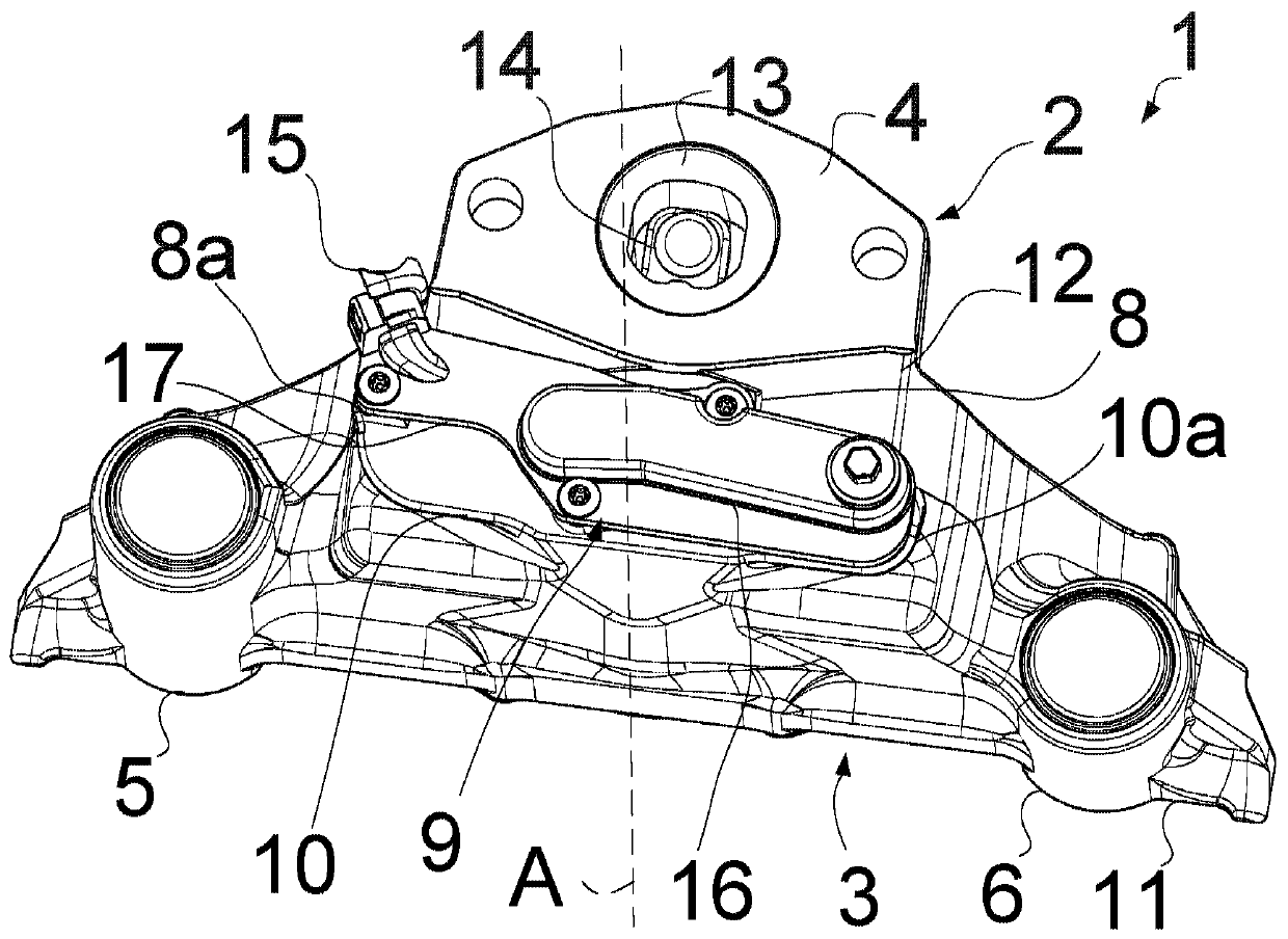
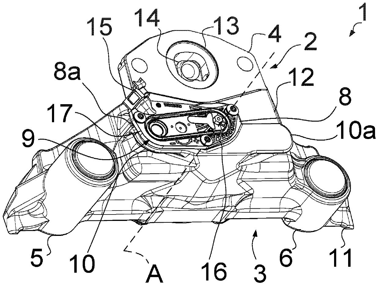
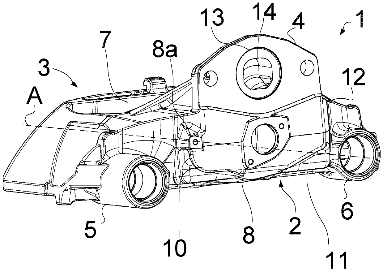
[0020] figure 1 The brake caliper 1 on the application side is shown. The brake caliper 1 is made of cast iron and has a brake cylinder flange surface 4 on the contact side 2 . An opening 13 for actuating a torsion bar 14 is arranged in the middle of the brake cylinder flange surface 4 . Between the pressure side 2 and the rim side 3, the brake caliper 1 has a brake disc opening 7 for receiving a not shown brake disc (cf. image 3 ). During the pressing process, the torsion bar 14 presses the brake disc via the pressing device. Two sliding sleeves 5 , 6 arranged axially parallel to the axis A of the brake caliper 1 move the brake caliper 1 axially on a not shown brake carrier during the braking process. Radially below the brake cylinder flange surface 4, in the direction of the first sliding sleeve 5 and the second sliding sleeve 6, the brake caliper 1 has a caliper housing 11 for receiving the flange surface 8, Subassembly 12 of 8a....


PUM


Abstract

The invention relates to a brake caliper of a disk brake for motor vehicles. The brake caliper (1) for a disc brake has a tensioning side (2) and a rim side (3) and bears a brake cylinder flange face(4), which, for receiving a brake cylinder, is disposed on the tensioning side (2). Two sliding bushes (5, 6) for an axial displacement of the brake caliper (1) are disposed on a brake support, and two flange faces (8, 8a) are disposed axially parallel to each other on the tensioning side (2) between the sliding bushes (5, 6) for receiving a sensor resetting unit (9).

Description

technical field [0001] The invention relates to a brake caliper for a motor vehicle disc brake, in particular for a truck. Calipers for disc brakes are well known. Numerous variants of brake calipers are known in the professional field. There are fixed calipers, floating calipers or oscillating calipers. The present invention relates to a floating caliper, in particular a single-piston floating caliper, also known as a single-piston floating caliper, wherein the floating caliper is also known by the term "sliding caliper" "known. The term "brake caliper" is used generally below. A brake caliper has a pinch side and a rim side. An opening is arranged between the pressure side and the rim side for receiving the brake disk, the rim-side brake lining and the pressure-side brake lining. The pressure device arranged on the pressure side within the brake caliper comprises a torsion bar, a spindle with a pressure plate and a pressure plate. The hold-down device presses the brak...

Claims


Application Information

Patent Timeline
Patent Type & Authority Applications(China)
IPC IPC(8): F16D65/18F16D65/095F16D66/00
CPCF16D65/18F16D65/095F16D66/00F16D55/226F16D65/0068F16D66/021F16D2055/0016F16D2200/0013F16D55/2265F16D2121/04
Inventor 贝恩沃德·雷德曼维塔利·舍雷尔马丁·斯顿夫
Owner ZF CV SYST EURO BV
Learn More