
Vehicle lamp

A technology of car lights and photons, applied in the field of lighting, to achieve the effect of clear low beam cut-off line, high center brightness, and overcoming effects that cannot be achieved at the same time

Pending Publication Date: 2020-03-24
YLX INC
View PDF1 Cites 4 Cited by
  • Summary
  • Abstract
  • Description
  • Claims
  • Application Information

AI Technical Summary

Problems solved by technology

In the present invention, by organically combining various technical features and using the ingenious design of the positional relationship between the various devices, the integrated far and near beam lighting with no bright and dark lines, clear cut-off line of low beam and high center brightness is realized, which overcomes the existing technology. Defects that cannot have both effects in

Method used


Image

  • Vehicle lamp
  • Vehicle lamp
  • Vehicle lamp

Examples


Embodiment 2

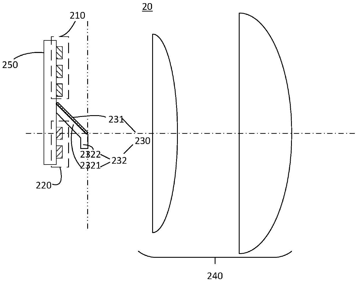
[0052] Both the carriers of Embodiment 2 and Embodiment 3 include a "transparent extension" arranged on the light output path of the second light-emitting sub-array. In the present invention, the projection of the transparent extension on the second light-emitting sub-array can be completely Covering the light-emitting surface of the second light-emitting sub-array. Such as Figure 5As shown, it is a front view of a vehicle lamp of the present invention (viewing angle against the direction of outgoing light). It includes a first light-emitting sub-array 1 , a second light-emitting sub-array 2 , a light-shielding surface 3 and a carrier 4 . Wherein, the second light-emitting sub-array 2 is behind the transparent extension part of the carrier 4, so it is represented by a dotted line.

[0053] In each of the embodiments listed above, both the first light-emitting sub-array and the second light-emitting sub-array are LED arrays, and the LED arrays are controlled by corresponding...


PUM


Abstract

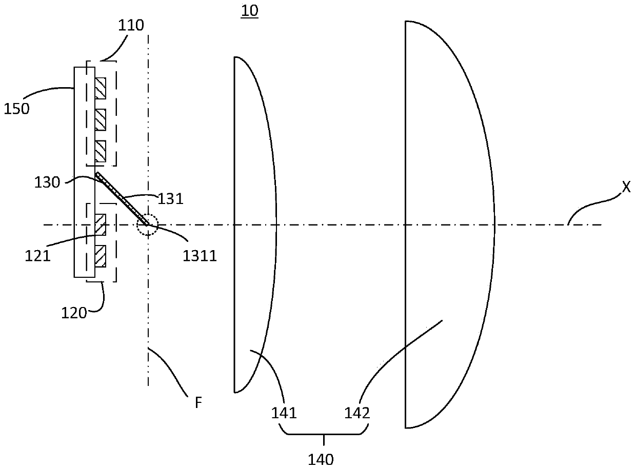
The invention provides a vehicle lamp, comprising a light-emitting array which comprises a first light-emitting sub-array and a second light-emitting sub-array which can be switched on and off independently; a projection lens, arranged on an emergent light path of the light-emitting array, the distance between the light-emitting array and the projection lens being larger than the focal length of the projection lens, and the second light-emitting sub-array at least comprising a light-emitting element arranged on the optical axis of the projection lens; a shading device, comprising a shading surface, the shading surface being obliquely arranged between the first light-emitting sub-array and the second light-emitting sub-array relative to the plane where the light-emitting array is located, and the shading surface inclining towards the second light-emitting sub-array. The shading surface comprises a first area far away from the light-emitting array. The first area is located on the frontfocal plane and the optical axis of the projection lens, and the first area comprises a low beam cut-off line contour. According to the vehicle lamp, high beam and low beam integrated automobile lampillumination which is free of bright and dark lines, clear in low beam cut-off line and high in center brightness is achieved.

Description

technical field [0001] The invention relates to the technical field of lighting, in particular to a vehicle lamp. Background technique [0002] Since the advent of LED car headlights in 2007, car headlights have gradually transitioned from halogen lamps and xenon lamps to LED lights. Especially in recent years, with the majestic development of new energy vehicles, LED lights have entered a stage of blowout development. LED car lights have the advantages of long life, low energy consumption and low cost compared with xenon lamps, and gradually cover from high-end cars to low-end cars. [0003] Existing LED car lights generally adopt the design idea of ​​the original halogen lamp, especially the far and near integrated headlight. This technical solution usually uses a high-brightness LED as the luminous center to replace the original halogen filament, and then collects the emitted light of the LED through a reflector, so that the emitted light of the LED converges at the hot...

Claims


Application Information

Patent Timeline
Patent Type & Authority Applications(China)
IPC IPC(8): F21S41/141F21S41/16F21S41/25F21S41/40F21W102/13F21W107/10
CPCF21S41/141F21S41/16F21S41/25F21S41/40F21W2102/13F21W2107/10F21S41/143F21S41/176F21S41/255F21S41/43
Inventor 张贤鹏马勇李明亮李屹
Owner YLX INC
Learn More