Ultra-deep sampling device for high turbidity water near the liquid surface and its application method

A sampling device and liquid surface technology, which is applied in the field of ultra-deep sampling devices for high turbidity water near the liquid surface, can solve the problems of equipment performance limitations, difficulty in collecting samples, easy damage to equipment, etc., and achieve the goal of eliminating head restrictions and reducing energy consumption Effect

Active Publication Date: 2022-04-05
BEIJING RESEARCH INSTITUTE OF CHEMICAL ENGINEERING AND METALLURGY
View PDF8 Cites 0 Cited by
  • Summary
  • Abstract
  • Description
  • Claims
  • Application Information

AI Technical Summary

Problems solved by technology

[0005] The purpose of the present invention is to provide an ultra-deep sampling device for high turbidity water near the liquid surface and its use method to solve the problem that the existing equipment is not easy to collect samples in ultra-deep wells, the collection is limited by the performance of the equipment and the collection contains a large amount of sediment The sample in the deep well is easy to damage the equipment

Method used


Image

  • Ultra-deep sampling device for high turbidity water near the liquid surface and its application method

Examples


Embodiment 1

[0022] Example 1: An ultra-deep sampling device for high turbidity water near the liquid surface.

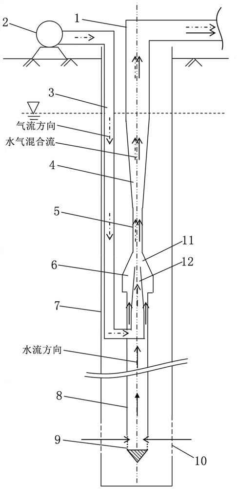
[0023] Such as figure 1 As shown, the ultra-deep sampling device facing the liquid surface of the present invention includes a jet 11 , an air pump 2 , a water inlet pipe 8 and a flower net pipe pendant 9 .

[0024] The ejector 11 can adopt the ejector sold on the market, and its structure comprises suction chamber 6, the nozzle 12 that is arranged in the suction chamber 6, the throat pipe 5 that is connected to the upper port of the suction chamber 6, joins with the upper port of the throat pipe 5 Diffusion section 4. A water outlet pipe 1 is connected to the upper port of the diffuser end 4 of the jet, and the other end of the water outlet pipe 1 leads to the ground and is connected with a sampling device arranged on the ground. The wall of the water outlet pipe 1 is marked with scale marks representing the length of the water outlet pipe 1 .

[0025] The air pump 2 is set ...

Embodiment 2

[0029] Embodiment 2: A method of using an ultra-deep sampling device for high turbidity water near the liquid surface.

[0030] The use method of the ultra-deep sampling device for high turbidity water near the liquid surface of the present invention comprises the following steps:

[0031] 1. Measure the distance between the well water level in the well to be sampled and the wellhead, and accordingly determine the depth of injection of the ejector 11 in the water well to be sampled, so that the ejector 11 can be submerged below the liquid level of the well water after delivery;

[0032] 2. According to the structural data of the well pipe 7 of the well to be sampled and the measured distance data from the well water surface to the wellhead, respectively calculate the distance between the filter 10 at the lower part of the well pipe and the well water liquid surface and the configuration of the required water inlet pipe length, and intercept the water inlet pipe 8 of correspond...


PUM


Abstract

The invention provides an ultra-deep sampling device for high turbidity water near the liquid surface and a method for using the same. The end of the diffusion section is connected with a water outlet pipe leading to the ground; the air pump is connected to the lower end of the nozzle in the suction chamber of the ejector through the air supply pipe, and is used to deliver high-pressure gas towards the diffusion section to the suction chamber, so that the water in the suction chamber moves along the outlet. The water pipe is transported to the ground; the upper end of the water inlet pipe is connected with the suction chamber of the ejector, and the lower end is connected with the flower net pipe pendant; the flower net pipe pendant is used to be installed at the filter at the bottom of the deep well to collect groundwater and provide the water inlet pipe with straightening The state's pulldown gravity. In the process of deep water sampling, the invention is not limited by the pressure resistance performance of equipment, and can also perform deep water sampling in water containing sediment.

Description

technical field [0001] The invention relates to a sampling device for ultra-deep well water, in particular to an ultra-deep sampling device for high turbidity water near the liquid surface and a method for using the same. Background technique [0002] At present, the monitoring methods of groundwater environment mainly adopt online monitoring and sampling detection. The monitoring items usually monitored online include water level, water temperature, conductivity and pH, etc. The monitored items are limited by the performance of online monitoring instruments and monitoring points, especially for large depth monitoring points under the liquid surface. Therefore, the comprehensive monitoring of groundwater environmental quality mainly depends on sampling and testing. In the process of sampling and testing, the degree of agreement between the test results of the collected samples and the actual situation often depends on the fidelity of the collected samples and the two main f...

Claims


Application Information

Patent Timeline
Patent Type & Authority Patents(China)
IPC IPC(8): G01N1/14
CPCG01N1/14G01N2001/1445G01N2001/1031
Inventor 温吉利胡鹏华赵传虎陈刚李海波王晓伟朱国明
Owner BEIJING RESEARCH INSTITUTE OF CHEMICAL ENGINEERING AND METALLURGY
Why Eureka
Try Eureka