Multi-microgrid cooperative control method and system, computer equipment and readable storage medium

A collaborative control, multi-microgrid technology, applied in the field of distribution network

Active Publication Date: 2020-03-24
SHENZHEN POWER SUPPLY BUREAU
View PDF3 Cites 0 Cited by
  • Summary
  • Abstract
  • Description
  • Claims
  • Application Information

AI Technical Summary

Problems solved by technology

[0003] The present invention aims to propose a multi-microgrid collaborative control and system, computer equipment, and comp...

Method used


Image

  • Multi-microgrid cooperative control method and system, computer equipment and readable storage medium
  • Multi-microgrid cooperative control method and system, computer equipment and readable storage medium
  • Multi-microgrid cooperative control method and system, computer equipment and readable storage medium

Examples


Embodiment 1

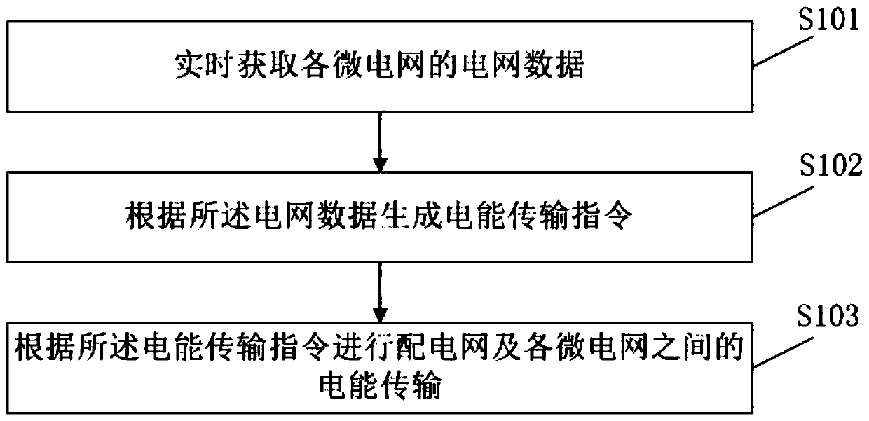
[0050] Embodiment 1 of the present invention proposes a multi-microgrid collaborative control method, figure 1 For the flowchart of the method described in embodiment one, refer to figure 1 , the method includes the following steps S101 to S103:

[0051] Step S101, acquiring grid data of each microgrid in real time;

[0052] Specifically, the grid data acquired in step S101 includes data such as the transmission power, voltage, and resistance of the DC lines between the microgrids, the AC lines between the microgrids and the AC distribution network, and the power generation of each microgrid. Device information, including charging and discharging power, load information of each microgrid, equipment operation and maintenance costs, etc.

[0053] Step S102, generating a power transmission instruction according to the grid data;

[0054] Specifically, the generated power transmission instruction is, for example, that the power of one of the micro-grids is not enough to supply ...

Embodiment 2

[0090] Embodiment 2 of the present invention proposes a multi-microgrid collaborative control system, which is used to implement the multi-microgrid collaborative control method described in Embodiment 1 of the present invention. Figure 6 For the framework diagram of the multi-microgrid collaborative control system described in Embodiment 2, refer to Figure 6 , the multi-microgrid collaborative control system described in Embodiment 2 includes:

[0091] The data acquisition unit 1 is configured to acquire grid data of each micro grid in real time;

[0092] The data processing unit 2 is configured to generate an electric energy transmission instruction according to the grid data;

[0093] The transmission execution unit 3 is configured to perform power transmission between microgrids according to the power transmission instruction.

[0094] Preferably, the data processing unit 2 includes:

[0095] The first determining unit 21 is configured to determine the electric energy...

Embodiment 3

[0107] Embodiment 3 of the present invention proposes a computer device, including: a memory and a processor, where computer-readable instructions are stored in the memory, and when the computer-readable instructions are executed by the processor, the processor executes according to The steps of the multi-microgrid collaborative control method described in Embodiment 1 of the present invention.

[0108] Of course, the computer device may also have components such as wired or wireless network interfaces, keyboards, and input / output interfaces for input and output, and the computer device may also include other components for realizing device functions, which will not be repeated here.

[0109] Exemplarily, the computer program may be divided into one or more units, and the one or more units are stored in the memory and executed by the processor to implement the present invention. The one or more units may be a series of computer program instruction segments capable of accomplis...


PUM


Abstract

The invention relates to a multi-microgrid cooperative control method and system, computer equipment and a readable storage medium, each microgrid is connected with a power distribution network through an alternating current line, adjacent microgrids are connected through a direct current line, and each microgrid comprises a power generation device and an electric energy storage device; the methodcomprises the following steps: acquiring power grid data of each microgrid in real time; generating an electric energy transmission instruction according to the power grid data; and performing electric energy transmission between the power distribution network and each microgrid according to the electric energy transmission instruction. The computer equipment comprises a controller and a memory storing computer programs for realizing the steps of the multi-microgrid cooperative control method, and the medium stores the computer programs for realizing the steps of the multi-microgrid cooperative control method. By implementing the invention, the problem of cooperative work after a plurality of microgrids are accessed to a large power grid can be solved.

Description

technical field [0001] The invention belongs to the field of distribution network technology, and in particular relates to a multi-micro-grid collaborative control and system, computer equipment, and a computer-readable storage medium. Background technique [0002] Microgrid is a kind of partial power grid, which is suitable for various distributed electric energy and different types of electric energy users, specifically a small distribution network system composed of distributed power supply, electric energy conversion device, energy storage device, etc. The microgrid can make the distributed power supply run flexibly and efficiently, and fully tap the value and benefits of distributed power generation. It is an optimal configuration of local distributed micro power supply or medium and small traditional power generation methods to provide electricity and heat to nearby loads. special grid. Among them, the scale of the microgrid is between the distributed generation and t...

Claims


Application Information

Patent Timeline
IPC IPC(8): H02J3/46H02J3/38
CPCH02J3/381H02J3/46
Inventor 王廷凰
Owner SHENZHEN POWER SUPPLY BUREAU
Why Eureka
Try Eureka