Wheel type vacuum chuck structure climbing cleaning trolley for glass curtain wall

A vacuum suction cup and glass curtain wall technology, applied in the field of climbing and cleaning trolleys, can solve the problems of high work intensity, prone to accidents, slow climbing, etc., and achieve the effect of high cleaning efficiency and efficient climbing

Active Publication Date: 2020-03-27
JINLING INST OF TECH
View PDF9 Cites 2 Cited by
  • Summary
  • Abstract
  • Description
  • Claims
  • Application Information

AI Technical Summary

Problems solved by technology

[0002] With the continuous development of society, there are more and more skyscrapers. In order to ensure the external cleaning of skyscrapers, it is often necessary to manually clean them outside. This is prone to accidents and the work intensity is often very high. Therefore, someone designed an external automatic cleaning mechanism. At present, the commonly used external automatic cleaning mechanisms include hanging automatic cleaning mechanisms and climbing cleaning trolleys. The hanging automatic cleaning mechanisms are limited by the slings and often can only clean low floors, so climbing cleaning trolleys are commonly used for skyscrapers. For building cleaning, since skyscrapers often use glass curtain walls, suction cup crawling robots are often used for climbing convenience. However, since this type of robot uses a vacuum suction cup structure for climbing, the traditional footed vacuum suction cup mechanism climbs slowly. Therefore, the applicant designs a wheeled vacuum sucker structure climbing cleaning trolley for glass curtain walls according to the characteristics of glass curtain walls.

Method used


Image

  • Wheel type vacuum chuck structure climbing cleaning trolley for glass curtain wall
  • Wheel type vacuum chuck structure climbing cleaning trolley for glass curtain wall
  • Wheel type vacuum chuck structure climbing cleaning trolley for glass curtain wall

Examples


Embodiment Construction

[0024] Below in conjunction with accompanying drawing and specific embodiment the present invention is described in further detail:

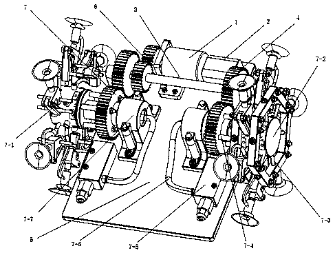
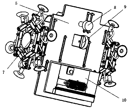
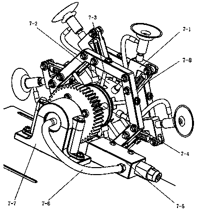
[0025] The invention provides a wheeled vacuum suction cup structure climbing and cleaning trolley for glass curtain walls. The vacuum suction cup structure adopts an original wheel structure, and the generation and destruction of vacuum in the gas path of different suction cups can be realized through the movement of two gas path components. Thereby climbing can be realized, and the cleaning of the glass curtain wall can be completed by cooperating with the corresponding cleaning mechanism.

[0026] As an embodiment of the present invention, the present invention provides such as Figure 1-2 Shown is a wheeled vacuum suction cup structure climbing cleaning trolley for glass curtain walls, including a motor 1, a battery pack 2, a gear shaft 3, a side drive gear set 4, a frame 5, a main drive gear set 6, and a wheeled suction cup Structure 7, bo...


PUM


Abstract

The invention discloses a wheel type vacuum chuck structure climbing cleaning trolley for a glass curtain wall. A motor and a battery pack are mounted on a frame; bottom auxiliary rotating wheels aremounted at the bottom of the frame through mounting frames; a cleaning mechanism is installed at the bottom of the rear end of the frame. A driving gear of the main driving gear set is mounted at theend of a rotating shaft of the motor; a driven gear of the main driving gear set is mounted on a gear shaft on one side of the motor; a pair of side driving gear sets is arranged; driving gears of theside driving gear sets are installed at the ends of the two sides of the corresponding gear shaft, driven gears of the side driving gear sets serve as driving mechanisms of the center air path assemblies to be arranged on steps of the tail air path assemblies of the corresponding wheel type vacuum suction cup structures in a sleeving mode, and the wheel type suction cup structures are arranged onthe two sides of the front end of the frame. According to the vacuum sucker structure, an original wheel type structure is adopted, vacuum generation and damage of different sucker air paths are achieved through movement cooperation of the two air path pieces, and therefore climbing is achieved, and cleaning of the glass curtain wall is completed in cooperation with the corresponding cleaning mechanism.

Description

technical field [0001] The invention relates to the field of climbing and cleaning trolleys, in particular to a climbing and cleaning trolley with a wheeled vacuum suction cup structure for glass curtain walls. Background technique [0002] With the continuous development of society, there are more and more skyscrapers. In order to ensure the external cleaning of skyscrapers, it is often necessary to manually clean them outside. This is prone to accidents and the work intensity is often very high. Therefore, someone designed an external automatic cleaning mechanism. At present, the commonly used external automatic cleaning mechanisms include hanging automatic cleaning mechanisms and climbing cleaning trolleys. The hanging automatic cleaning mechanisms are limited by the slings and often can only clean low floors, so climbing cleaning trolleys are commonly used for skyscrapers. For building cleaning, since skyscrapers often use glass curtain walls, suction cup crawling robots...

Claims


Application Information

Patent Timeline
Patent Type & Authority Applications(China)
IPC IPC(8): A47L11/38A47L11/40A47L1/02E04G23/00B62D57/024
CPCA47L1/02A47L11/38A47L11/4005A47L11/4066A47L11/4083A47L11/4088B62D57/024E04G23/002
Inventor 李晓晖陆俊杰姚科姜宇航吴佳浩
Owner JINLING INST OF TECH
Why Eureka
Try Eureka