
Infusion stand base

The technology of an infusion stand and a stand rod is applied in the field of medical devices, which can solve the problems of being difficult to fix, easy to trip, and inconvenient to move, and achieves the effects of high stability, easy storage and transportation, and easy storage and transportation.

Inactive Publication Date: 2020-03-27
吕辉
View PDF0 Cites 0 Cited by
  • Summary
  • Abstract
  • Description
  • Claims
  • Application Information

AI Technical Summary

Problems solved by technology

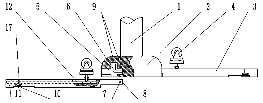
[0003] In order to ensure that the infusion stand does not fall over after being placed, the bottom of the infusion stand is fixedly provided with a support seat. Generally, the support seat of the infusion stand is divided into two types: movable and immovable; the immovable infusion stand can only be fixed in one position. Its quality is relatively heavy, and it is inconvenient to move, so it is not popular; the movable support frame is equipped with moving wheels at the bottom of the supporting legs, and the moving wheels can facilitate the movement of the infusion stand. , so that the support point is on the moving wheel, which is not easy to fix, and the stability is not good; in addition, the moving wheel is fixed on the bottom of the supporting leg, which increases the height of the supporting leg, and it is easy to trip doctors or family members passing by or visiting relatives and friends , Seriously bring the rod down, so that the needle is pulled out by mistake, and the patient is injured

Method used


Image

  • Infusion stand base
  • Infusion stand base
  • Infusion stand base

Examples


Embodiment Construction

[0019] The embodiment given below intends to further illustrate the present invention, but can not be interpreted as the restriction to protection scope of the present invention, those skilled in the art still belongs to the protection of the present invention to some non-essential improvements and adjustments of the present invention according to the content of the present invention scope.

[0020] Unless expressly stated otherwise, throughout the specification and claims, the term "comprise" or variations thereof such as "includes" or "includes" and the like will be understood to include the stated elements or constituents, and not Other elements or other components are not excluded.

[0021] In the description of the present invention, it should be noted that the terms "center", "upper", "lower", "left", "right", "vertical", "horizontal", "inner", "outer" etc. The indicated orientation or positional relationship is based on the orientation or positional relationship shown ...


PUM


Abstract

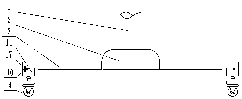
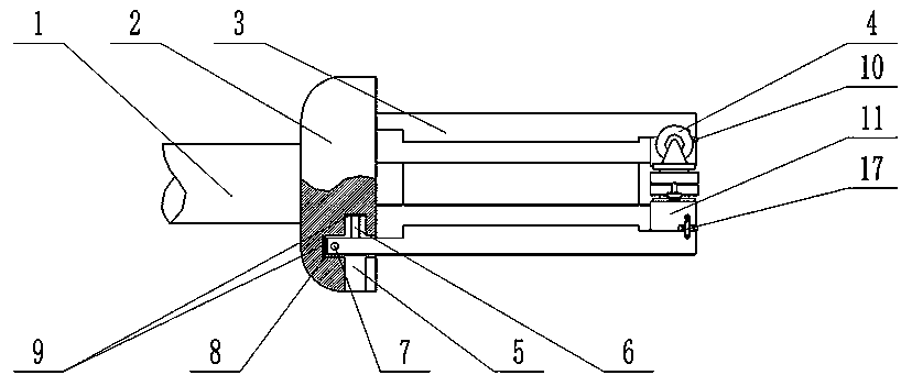
The invention discloses an infusion stand base. The infusion stand base is characterized by comprising a stand rod, a support base, support legs, and movable wheels; the stand rod is perpendicularly and fixedly mounted at the top of the support base; cross grooves are provided on side parts of the support base; one ends of the support legs are placed in the cross grooves, so that the support legscan be horizontally or vertically connected with the support base under the action of the cross grooves; the other ends of the support legs are hinged with flip legs by hinges; T-shaped grooves are provided on both the support legs and the flip legs; sliders are placed inside the T-shaped grooves; supporting shafts are sleeved with positioning valves; end parts of the positioning valves can abut against top parts of the sliders so as to have the sliders fixed inside the T-shaped grooves; the T-shaped grooves on the support legs communicate with the T-shaped grooves on the flip legs; connectingplates are hinged, at hinge joints of the support legs and the flip legs, with side parts of the support legs; fixing columns are provided on corresponding side parts of the flips; arc-segment-shapedopenings are provided, at positions corresponding to the fixing columns, on the connecting plates; and the arc-segment-shaped openings can be clamped on the fixing columns. The infusion stand base has the following advantages: the infusion stand base is convenient to store, high in stability, and convenient to move.

Description

technical field [0001] The invention belongs to the technical field of medical devices, and in particular relates to a transfusion stand base. Background technique [0002] The infusion stand is a support device used in hospitals to hang water for patients. When in use, install the hanging bottle in the hanging bottle frame, and then hang the hanging bottle frame on the hook on the infusion stand, and the liquid in the hanging bottle will automatically Flow up and down into the patient's body. [0003] In order to ensure that the infusion stand does not fall over after being placed, the bottom of the infusion stand is fixedly provided with a support seat. Generally, the support seat of the infusion stand is divided into two types: movable and immovable; the immovable infusion stand can only be fixed in one position. Its quality is relatively heavy, and it is inconvenient to move, so it is not popular; the movable support frame is equipped with moving wheels at the bottom of...

Claims


Application Information

Patent Timeline
Patent Type & Authority Applications(China)
IPC IPC(8): A61M5/14
CPCA61M5/1415
Inventor 吕辉
Owner 吕辉
Learn More