

Multi-station automobile part laser welding equipment
A technology of auto parts and laser welding, which is applied in laser welding equipment, welding equipment, metal processing equipment, etc., can solve the problems of low adjustability and inability to correct the welding effect, and achieve the effect of improving operation accuracy
- Summary
- Abstract
- Description
- Claims
- Application Information
AI Technical Summary
Problems solved by technology
Method used
Image

Examples
Embodiment 1
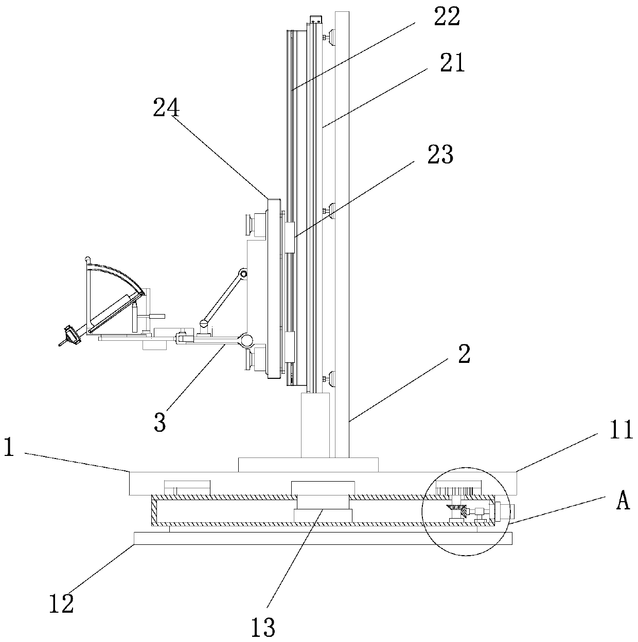
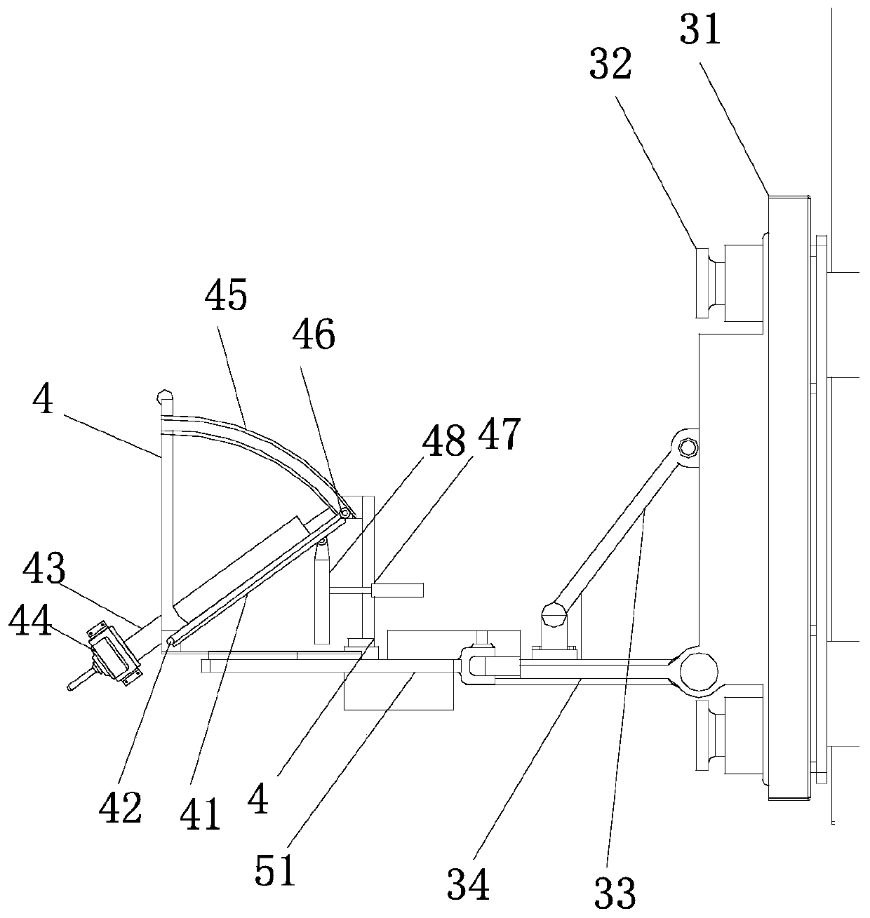
[0028] see figure 1 , a multi-station laser welding equipment for auto parts, comprising a base 1, a support frame 2 is installed on the base 1, a vertical frame plate 21 is installed on the support frame 2, and the vertical frame plate A vertical guide rail 22 is installed on the 21, a bearing plate 24 is installed on the vertical guide rail 22 through a sliding connection seat 23, and a work frame 3 is installed on the bearing plate 24. The rear side of the work frame 3 is provided with an installation base plate 31, the installation base plate 31 is fixedly installed on the carrier plate 24 through a locking bolt 32, and the front end of the installation base plate 31 is equipped with an operation frame plate 34, the operation frame A reinforcing bracket 33 is erected between the board 34 and the installation base plate 31 in an oblique direction.
[0029] The work frame 3 is a frame used for welding operations. In this application, the work frame 3 is installed on the ver...
Embodiment 2
[0037] see figure 1 and Figure 5, this embodiment is a further optimization of the first embodiment, on the basis of which, the base 1 includes a fixed seat 12 and a steering seat 11, and the steering seat 11 is installed on the top of the fixed seat 12 through the main steering shaft 13, so There is an annular groove 14 on the bottom plane of the steering seat 11, the inner edge of the annular groove 14 is provided with annular teeth 15, the inner cavity of the fixed seat 12 is set as an inner hollow structure, and a power input is installed in the fixed seat 12. Shaft 16, the top end of the power input shaft 16 is equipped with a driving gear 17, and the driving gear 17 is meshed with the ring gear 15. The fixed seat 12 is externally equipped with a driving motor 10, a driving helical gear 18 is installed on the driving end of the driving motor 10, a driven helical gear 19 is installed on the power input shaft 16, and the driven helical gear 19 It meshes with the driving ...
PUM
 Abstract
Description
Claims
Application Information