Supercharge Your Innovation With Domain-Expert AI Agents!

Material forming device

A material forming device and material technology, applied in the direction of metal processing, etc., can solve the problems of equipment cost impact, affecting work efficiency, slow conveyor belt transmission frequency, etc.

Pending Publication Date: 2020-03-27
台州市德来力包装设备有限公司
View PDF1 Cites 0 Cited by
  • Summary
  • Abstract
  • Description
  • Claims
  • Application Information

AI Technical Summary

Problems solved by technology

The existing material forming device will first drop onto the conveyor belt after cutting, such as the Chinese invention patent with patent number 201610376826.7, which is first conveyed to the material block conveying device through the conveyor belt, and then conveyed to the packaging equipment through the material block conveying device However, due to the slow conveying frequency of the conveyor belt, this seriously affects the work efficiency, and the additional conveyor belt and driving device will also affect the cost of the equipment; therefore, it is necessary to improve

Method used


Image

  • Material forming device
  • Material forming device

Examples


Embodiment 1

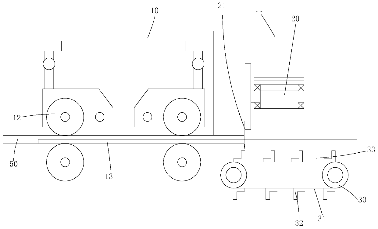
[0012] Example 1, see figure 1 Shown: a material forming device, including a body, a material strip conveying device, a material cutting device and a material block conveying device, the body is composed of a front frame 10 and a rear frame 11, and the material strip conveying device is arranged on the front frame 10 on, and there is a feeding motor and a feeding pinch wheel 12 on it, and the feeding motor is connected with the feeding pinch wheel 12 and drives it to rotate; on the front frame 10, there is a material bar guide groove 13 that is used in conjunction with the feeding pinch wheel 12, and the material bar The guide groove 13 can place the strip-shaped material 50 , which can move in the material strip guide groove 13 under the action of the feeding pinch wheel 12 . The material cutting device is located on the rear frame 11 and cooperates with the discharge port of the material bar guide groove. The structure of the material cutting device can be: comprising a rota...

Embodiment 2

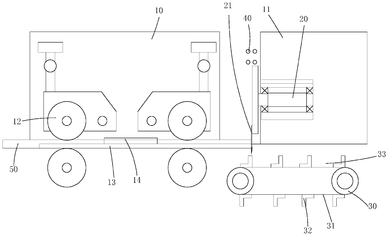
[0013] Example 2, see figure 2 As shown: the structure of embodiment 2 is roughly the same as that of embodiment 1, the difference is that: the material cutting device has an electromagnetic induction heater 40, and the electromagnetic induction heater 40 has a section for the cutting tool 21 to pass through and cut its magnetic field ; When the cutting tool 21 passes through this section, it will cut the magnetic field at this position, thereby generating an alternating current, allowing the cutting tool 21 to generate heat, thereby melting the material particles sticking to it, so that the cut material automatically falls off. There is a pressing plate 14 on the material bar guide groove 13, and the material bar 14 can prevent the material bar from falling out of the material bar guide groove 13, and plays a better positioning role.


PUM


Abstract

The invention discloses a material forming device, which comprises a machine body, a material bar conveying device, a material cutting device and a material block conveying device. The material bar conveying device is located on the machine body and is used in cooperation with a material bar guide groove on the machine body. The material cutting device is located on the machine body and is used incooperation with the outlet of the material bar guide groove. The material block conveying device is composed of a driving motor, a driving wheel, a driving chain and pushing hooks. The driving wheelis connected to the driving motor. The driving chain sleeves the driving wheel and rotates with the driving wheel. The pushing hooks are fixedly arranged on the driving chain and material accommodating sections are formed between adjacent material hooks. The material accommodating sections are located below the outlet of the material bar guide groove. The material forming device can improve workefficiency and is low in cost.

Description

technical field [0001] The invention belongs to the technical field of food material cutting machines, and in particular relates to a material forming device. Background technique [0002] At present, most foods need to be packaged in plastic packaging bags, such as candies, cakes and other strip-shaped packaged foods; Reach the required length and seal the package. The existing material forming device will first drop onto the conveyor belt after cutting, such as the Chinese invention patent with patent number 201610376826.7, which is first conveyed to the material block conveying device through the conveyor belt, and then transported to the packaging equipment through the material block conveying device However, due to the slow conveying frequency of the conveyor belt, this seriously affects the work efficiency, and the additional conveyor belt and driving device will also affect the cost of the equipment; therefore, it is necessary to improve it. Contents of the inventi...

Claims


Application Information

Patent Timeline
Patent Type & Authority Applications(China)
IPC IPC(8): B26D1/29B26D7/32
CPCB26D1/29B26D7/32B26D2210/02
Inventor 陈方林
Owner 台州市德来力包装设备有限公司
Features
  • R&D
  • Intellectual Property
  • Life Sciences
  • Materials
  • Tech Scout
  • Unparalleled Data Quality
  • Higher Quality Content
  • 60% Fewer Hallucinations
Learn More