An automatic stamping machine that is convenient for adding ink pads

An automatic stamping machine and printing pad technology, applied in the field of stamping machines, can solve the problems of contamination, affecting stamping efficiency, and difficulty in grasping the position and direction of stamping.

Active Publication Date: 2021-04-30
中迪环境工程有限公司
View PDF15 Cites 3 Cited by
  • Summary
  • Abstract
  • Description
  • Claims
  • Application Information

AI Technical Summary

Problems solved by technology

[0003] The traditional manual stamping can no longer meet the requirements of the current stage. It is difficult to grasp the position and direction of the stamping method by hand, and in order to ensure the clarity of the stamp pattern, it needs to be frequently contaminated with ink pad when stamping, which greatly affects the accuracy of stamping. efficiency
[0004] In addition, manual stamping requires frequent taking or placing of data files, and people's hands are frequently in contact with data files, which can easily cause data files to wrinkle and become dirty

Method used


Image

  • An automatic stamping machine that is convenient for adding ink pads
  • An automatic stamping machine that is convenient for adding ink pads
  • An automatic stamping machine that is convenient for adding ink pads

Examples


no. 1 example

[0020] Such as figure 1 As shown, an automatic stamping machine that is convenient for adding ink pads includes a base 1, a bracket 2 and a slider 3, a bracket 2 is installed on the right side of the top of the base 1, the bracket 2 is perpendicular to the base 1, and the bracket 2 is slidably provided with The slider 3, the slider 3 can slide vertically on the bracket 2, and also includes the outer casing 4, the mounting plate 5, the first spring 6, the stamp mechanism 7, the electric paper output roller 8 and the pressure wheel 9, the slider The left end face of 3 is connected with outer casing 4, and outer casing 4 is parallel to base 1, is provided with mounting plate 5 slidingly in outer casing 4, and mounting plate 5 can slide up and down in outer casing 4, and mounting plate 5 and outer casing 4 The first spring 6 is connected between them, the bottom of the mounting plate 5 is provided with a stamping mechanism 7 that can move thereon, the left and right sides of the b...

no. 2 example

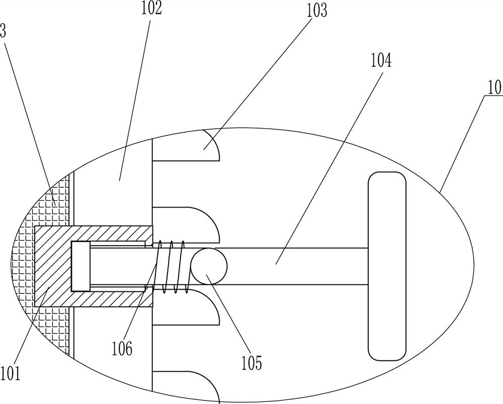
[0025] On the basis of the first embodiment, such as image 3 As shown, a fixed assembly 10 is also included, and the fixed assembly 10 includes a sliding frame 101, convex teeth 103, connecting rod 104, clamping rod 105 and a third spring 106, the right side of the slider 3 is fixedly connected with the sliding frame 101, and the bracket 2 There is a chute 102 for the passage of the sliding frame 101 on the right side. A connecting rod 104 is slidably connected in the sliding frame 101. The connecting rod 104 can move left and right in the sliding frame 101. Between the connecting rod 104 and the right end of the sliding frame 101 A third spring 106 is connected, and the third spring 106 is sleeved on the outside of the connecting rod 104 . The middle part of the connecting rod 104 is connected with a clamping rod 105 .

[0026]When the outer casing 4 moves downward freely and drives the slider 3 to move downward, it drives the slide frame 101 to move downward through the chu...

no. 3 example

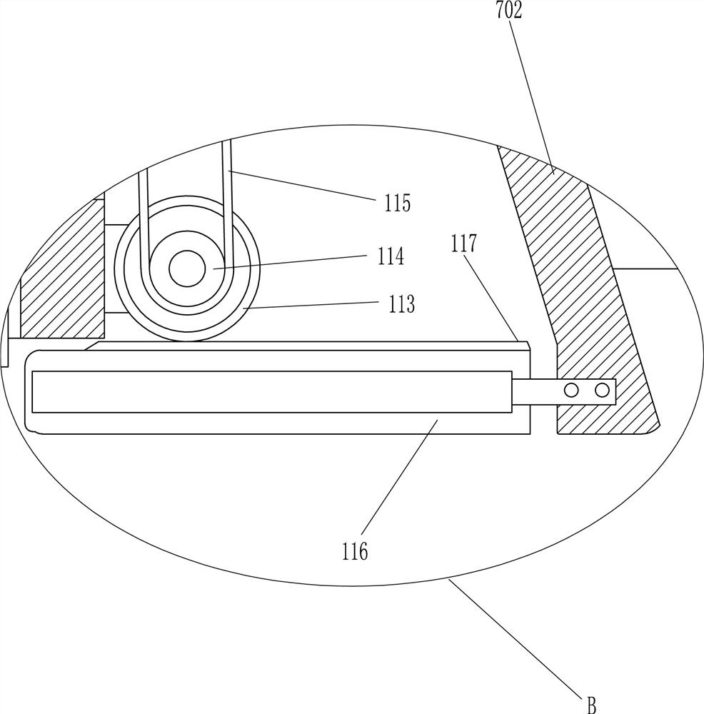
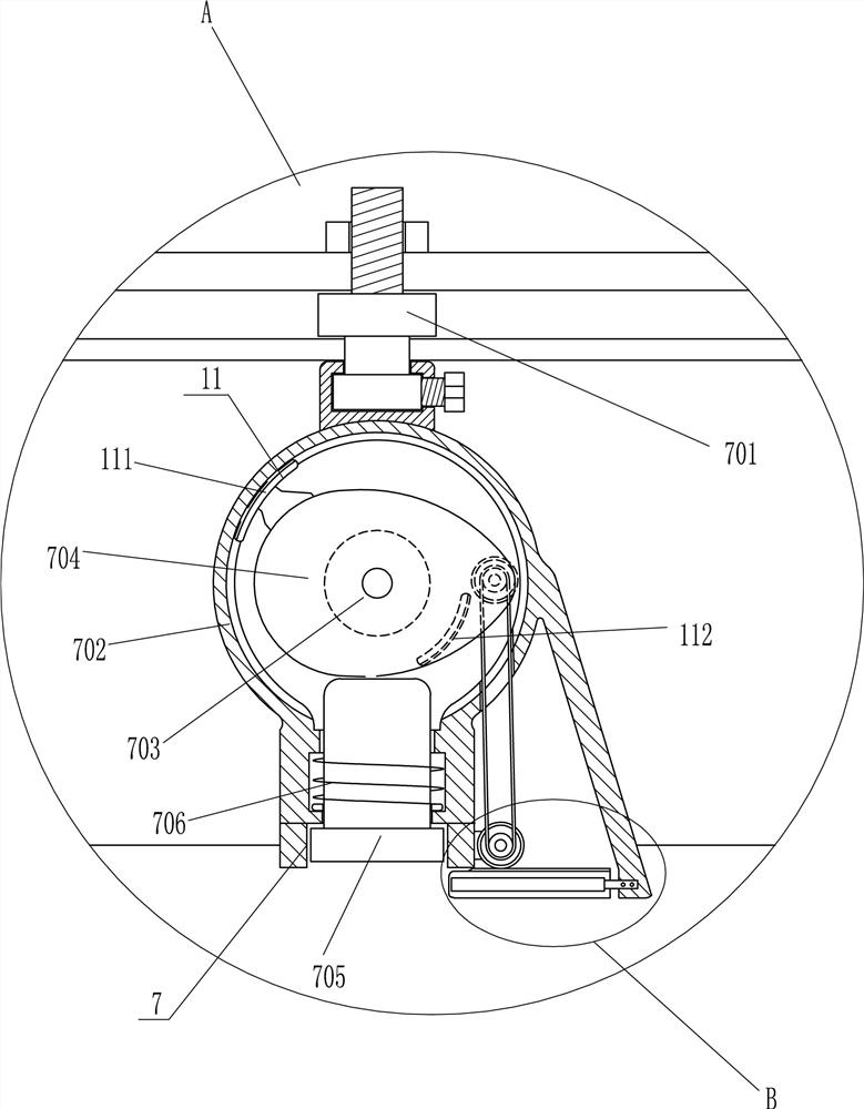
[0028] On the basis of the second embodiment, such as figure 2 and Figure 4 As shown, also include feeding device 11, feeding device 11 includes outer arc rack 111, inner arc rack 112, gear 113, sprocket wheel 114, chain 115, ink pad box 116 and transmission rack 117, The bottom of the right side of the inner shell 702 is slidingly connected with an ink pad box 116, which is set horizontally, and the top of the ink pad box 116 is connected with a transmission rack 117, which is connected to the ink pad box 116 by bolts, elliptical The cam 704 is connected with an outer arc rack 111 and an inner arc rack 112, the right side of the inner middle part of the inner housing 702 and the outer lower right side of the inner housing 702 are rotatably connected with a gear 113, and the outer arc rack 111 and the inner arc rack 112 can be meshed with the gear 113, the upper and lower two gears 113 are connected with a sprocket 114, and the upper and lower two sprockets 114 are connecte...


PUM


Abstract

The invention relates to a stamping machine, in particular to an automatic stamping machine which is convenient for adding ink pads. The technical problem is how to design a kind of automatic stamping machine that can facilitate the stamp to be stained with ink pad, guarantee the efficiency of stamping, and can not require people to frequently take or place data files, and ensure that the data files are neat and convenient to add ink pads. An automatic stamping machine that is convenient for adding ink pads, including a base, a bracket, a slider, an outer shell, a mounting plate, a first spring, etc.; a bracket is installed on the right side of the top of the base, and a sliding block is provided on the bracket. An outer casing is connected to the left end surface of the outer casing, and a mounting plate is slidably provided in the outer casing. The mounting plate can slide up and down in the outer casing, and a first spring is connected between the mounting plate and the outer casing. The present invention can quickly seal the document through the function of the stamping mechanism, and can adjust the left and right, front and rear positions of the stamping mechanism before stamping, and can conveniently stamp various parts of the document.

Description

technical field [0001] The invention relates to a stamping machine, in particular to an automatic stamping machine which is convenient for adding ink pads. Background technique [0002] Seals are used as stationery printed on documents to indicate identification or signature. Generally, stamps are first stained with paint and then printed. Those that do not stain with paint and will appear concave and convex after being printed on a flat surface are called steel seals. Some are printed on wax or wax. Wax stamp on envelope. The production materials are metal, wood, stone, jade and so on. Seals, as a representation of personal identity and unit attributes, have been widely used as a voucher since ancient times. The development of the economy and society has driven the improvement of the financial management of the whole society. More and more attention has been paid to the vouchers for stamping financial documents. At the same time, the surge in usage has put forward higher ...

Claims


Application Information

Patent Timeline
Patent Type & Authority Patents(China)
IPC IPC(8): B41K3/04B41K3/56
CPCB41K3/04B41K3/56
Inventor 蒋志进
Owner 中迪环境工程有限公司
Why Eureka
Try Eureka