A bridge deck wet joint joint and its construction method and application

A construction method and wet joint technology, applied in bridges, bridge materials, bridge construction, etc., can solve problems such as difficulty in welding and binding of lower steel bars, and impact on project progress, so as to reduce construction difficulty, improve bearing capacity, and avoid construction. effect of delay

Active Publication Date: 2020-09-22
SHANDONG UNIV +1
View PDF8 Cites 0 Cited by
  • Summary
  • Abstract
  • Description
  • Claims
  • Application Information

AI Technical Summary

Problems solved by technology

However, the inventor has found in long-term engineering practice that the existing wet joints in the form of such straight steel bars have the problem of difficult welding and binding of the lower steel bars during construction; both ends of the U-shaped steel bars are all anchored to the In the panel, the rigidity is high. If the relative position of the prefabricated bridge deck needs to be adjusted, the U-shaped steel bars are difficult to bend. This requires that the positioning of the prefabricated bridge deck needs to be very precise, but it is difficult to guarantee this every time in actual engineering. accuracy, which has a great impact on the progress of the project

Method used


Image

  • A bridge deck wet joint joint and its construction method and application
  • A bridge deck wet joint joint and its construction method and application
  • A bridge deck wet joint joint and its construction method and application

Examples


no. 1 example

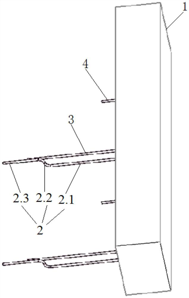
[0040] first embodiment ,refer to figure 1 , an example of a single-side bridge deck wet joint joint designed by the present invention, including: a prefabricated bridge deck 1, bent steel bars 2, long straight bars 3 and short straight bars 4.

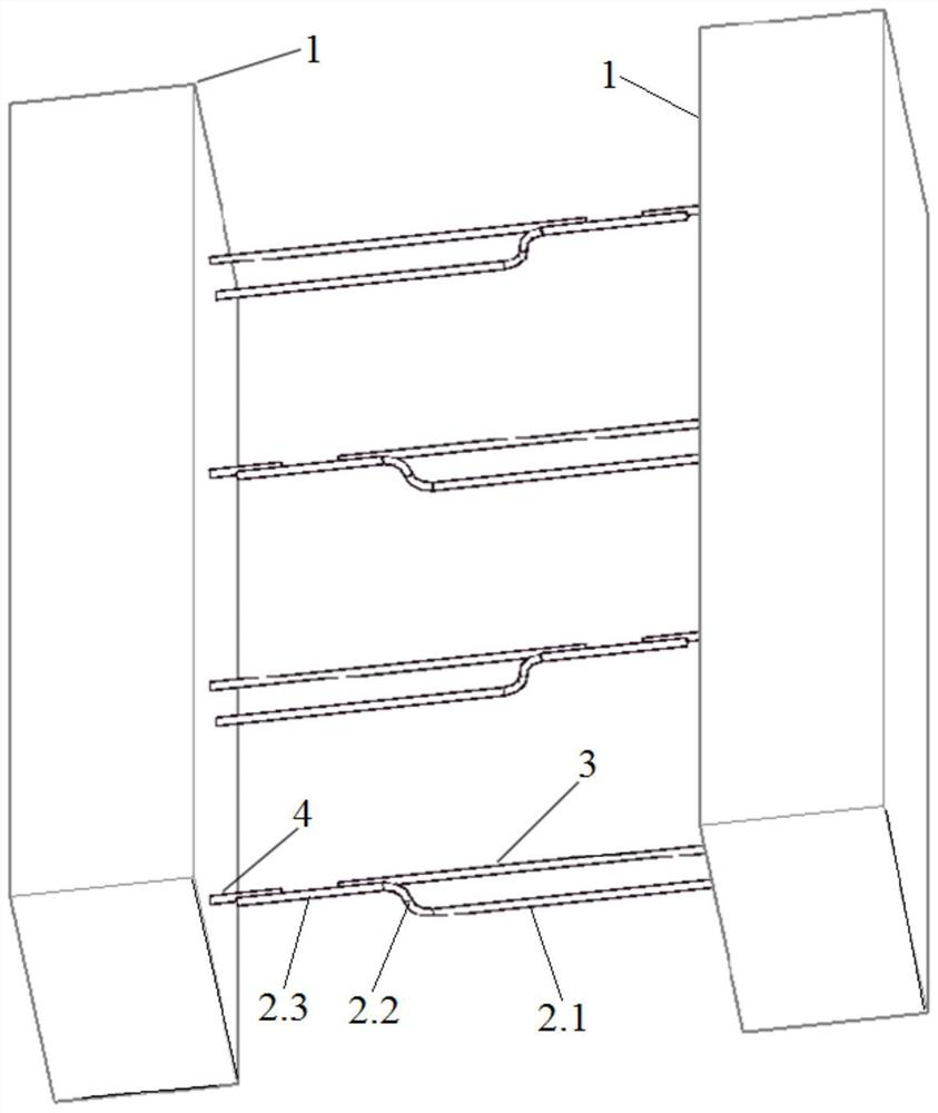
[0041]The side walls of the prefabricated bridge deck 1 are fixed with curved steel bars 2, long straight steel bars 3, and short straight steel bars 4, wherein one end of each of the long straight steel bars 3 and short straight steel bars 4 is anchored in the prefabricated bridge deck 1 , and the long straight bars 3 and the short straight bars 4 are staggered along the length direction of the wet joint.

[0042] The bent steel bar 2 includes a lower straight steel bar section 2.1, a curved arc-shaped steel bar section 2.2, and an upper straight steel bar section 2.3. One end of the lower straight steel bar section 2.1 is fixed in the prefabricated bridge deck, and the curved arc The two ends of the shaped steel bar section 2.2 a...

no. 2 example

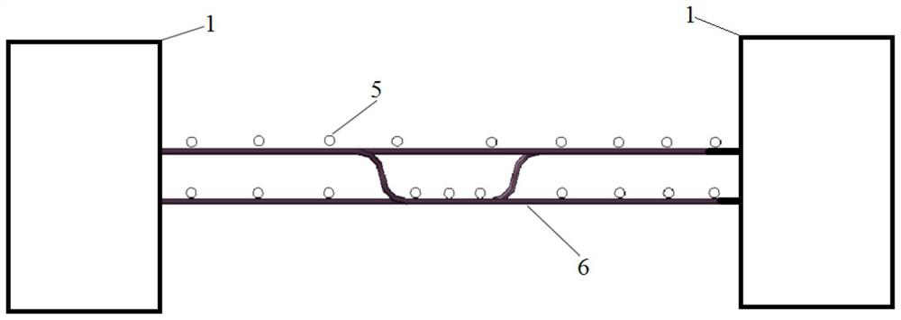
[0044] second embodiment , the bridge deck wet joint joint also includes two layers of longitudinal reinforcement 5, which are distributed along the length direction of the wet joint, wherein one layer of longitudinal reinforcement 5 is tied to the long straight reinforcement 3, the short straight reinforcement 4, and the upper straight reinforcement section 2.3 Together, another layer of longitudinal reinforcement 5 and the lower layer of straight reinforcement section 2.1 are tied together, so that the longitudinal reinforcement 5 and the wet joint joint of the bridge deck form a whole and jointly bear force.

no. 3 example

[0045] third embodiment , the bending line type of the curved arc-shaped steel bar section 2.2 is two semi-circular arcs with symmetrical center and equal radius, the arc radius R=H / 2, H is the long straight steel bar 3 and the lower straight steel bar Vertical straight-line distance between paragraphs 2.1.


PUM


Abstract

The invention belongs to the technical field of bridge engineering, and particularly relates to a bridge deck wet joint connector and a construction method and application thereof. The structure of the joint is as follows: the joint is cylindrical; bent steel bars, long straight steel bars and short straight steel bars are arranged on the side wall of the prefabricated bridge deck slab, wherein one end of each of the long straight reinforcing steel bars and the short straight reinforcing steel bars is fixed in the prefabricated bridge deck slab; the long straight steel bars and the short straight steel bars are distributed in a staggered manner along the length direction of the wet joint; the bent reinforcing steel bar comprises a lower-layer straight reinforcing steel bar section, a bentarc reinforcing steel bar section and an upper-layer straight reinforcing steel bar section; one end of the lower-layer straight steel bar section is fixed in the prefabricated bridge deck slab, the two ends of the bent arc-shaped steel bar section are connected with the lower-layer straight steel bar section and the upper-layer straight steel bar section respectively, the lower-layer straight steel bar section is longer than the upper-layer straight steel bar section, and the upper-layer straight steel bar section, the long straight steel bars and the short straight steel bars are fixed together to form a whole. According to the wet joint connector, the construction difficulty can be remarkably reduced, the construction progress can be accelerated, and the relative position of the bridgedeck slab can be conveniently adjusted.

Description

technical field [0001] The invention belongs to the technical field of bridge engineering, and in particular relates to a bridge deck wet joint joint, a construction method and application thereof. Background technique [0002] The information disclosed in the Background of the Invention is only intended to increase the understanding of the general background of the invention, and it is not necessarily to be taken as an acknowledgment or any form of suggestion that the information constitutes the prior art that is already known to those skilled in the art. [0003] Wet joints refer to prefabricated prestressed concrete beams divided into pieces, cantilever assembled into large-span continuous beams, and cast-in-place concrete is used between beams to connect beams into a whole. In the structural form of prefabricated composite bridges, prefabricated The panel wet joint is the key to affect the field assembly speed and the mechanical performance of the structure. At present,...

Claims


Application Information

Patent Timeline
Patent Type & Authority Patents(China)
IPC IPC(8): E01D19/12E01D21/00E01D101/26
CPCE01D19/125E01D21/00E01D2101/26
Inventor 王有志邱凯曾继祚曹善庆徐皓苏栋赵立鹏
Owner SHANDONG UNIV
Why Eureka
Try Eureka