
An anti-theft aluminum alloy door and window

An aluminum alloy door and window, anti-theft technology, applied in the field of doors and windows, can solve the problems of limited door opening angle, single locking position between the door and the door frame, and reduced door safety and anti-theft coefficient, so as to increase circulation, increase flexibility, Addressing space-occupying effects

Active Publication Date: 2021-04-27
常州市众鑫装饰工程有限公司
View PDF4 Cites 0 Cited by
  • Summary
  • Abstract
  • Description
  • Claims
  • Application Information

AI Technical Summary

Problems solved by technology

[0004] In order to make up for the deficiencies of the prior art, to solve the problem that the opening angle of the door is limited, the flow rate of the door frame is affected, and the locking position between the door and the door frame is single, and the safety and anti-theft coefficient of the door is reduced, the present invention proposes an anti-theft Type aluminum alloy doors and windows

Method used


Image

  • An anti-theft aluminum alloy door and window
  • An anti-theft aluminum alloy door and window
  • An anti-theft aluminum alloy door and window

Examples


Embodiment approach

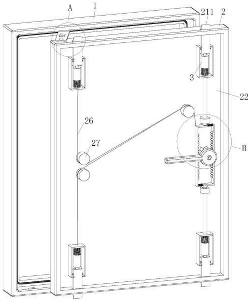
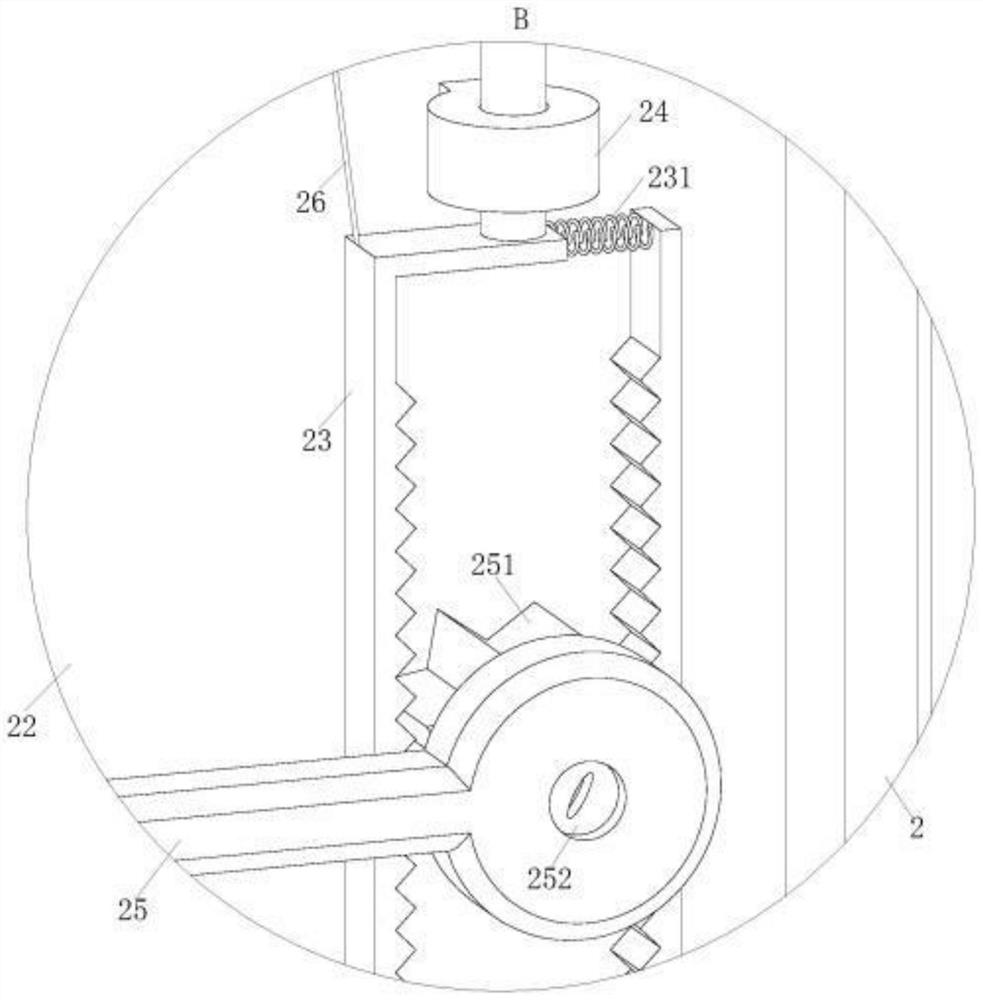
[0024] As a specific embodiment of the present invention, the telescopic unit 3 includes a sleeve 31, a push rod 32, a turntable 33 and a U-shaped block 34; the outer ring of the sleeve 31 is fixed on the side wall of the first cavity 22 , a guide rail 311 is provided symmetrically in the sleeve 31, and the guide rail 311 is embedded in the No. 2 chute 321 provided on the ejector rod 32; The tip on the rod 32 fits the slope on the turntable 33; the lower end of the turntable 33 is connected to the U-shaped block 34 through the second spring 331, and the upper end of the U-shaped block 34 is buckled on the stopper 212 provided on the clamping block 211 ; Through the cooperation between the telescopic unit 3 and the clamping block 211, the clamping block 211 is snapped into the No. 1 slot 11, and the clamping block 211 is retracted into the No. 1 through hole 21; when working, the working of the telescopic unit 3 The principle is the same as the working principle of pressing the...

specific Embodiment approach

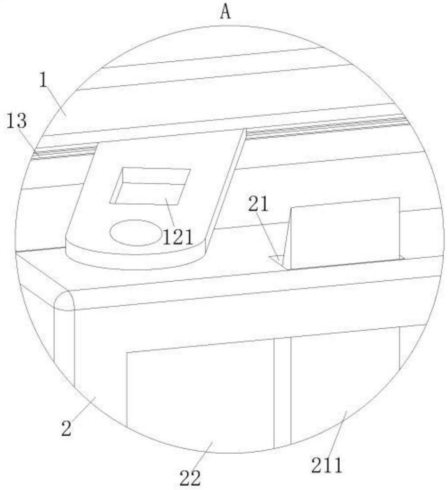
[0026] As a specific embodiment of the present invention, No. 2 through hole 121 is provided on the No. 1 plate 12, and when the door 2 is attached to the door frame 1, No. 1 groove 11 communicates with No. 2 through hole 121; hole 121, to further fasten the gap between the door 2 and the door frame 1; when working, if the clamping block 211 works for a long time, there will be a gap between the clamping block 211 and the No. 1 slot 11, resulting in a gap between the door 2 and the door frame 1 Loose phenomenon occurs between the door 2 and the door frame 1. When the door 2 and the door frame 1 are attached, that is, the door 2 is in the closed state. At this time, the second through hole 121 of the first plate 12 and the first groove 11 connected, and then the clamping block 211 extends into the first slot 11 through the second through hole 121, the clamping block 211 secures the first plate 12 on the door frame 1, and the first plate 12 fastens the door 2 in the door frame 1 ...


PUM


Abstract

The invention belongs to the technical field of doors and windows, and specifically relates to an anti-theft aluminum alloy door and window. The other end of the door is hinged on the upper and lower frames of the door; No. 1 through hole is symmetrically opened on the upper and lower frames of the door, and a snap-in block is arranged in the No. 1 through-hole; the lower end of the snap-in block is connected to the telescopic unit; The No. 1 rack is connected with the No. 1 rack. The No. 1 racks are arranged symmetrically in the center, and the No. 1 racks are connected by the No. 1 spring. Each No. 1 rack is respectively connected to the No. 1 gear on the door handle. Engagement; the telescopic unit close to the No. 1 plate is connected to the upper end surface of the No. 1 rack near the No. 1 plate through the No. 1 rope and multiple fixed pulleys; through the door handle, the telescopic unit, the clamping block and the No. 1 slot Fit to achieve a tight fit between the door and the door frame.

Description

technical field [0001] The invention belongs to the technical field of doors and windows, in particular to an anti-theft aluminum alloy door and window. Background technique [0002] Doors and windows are indispensable building industrial products for human living houses. Aluminum alloy windows are windows with frames and fan structures made of aluminum alloy building profiles, which are divided into ordinary aluminum alloy doors and windows and broken bridge aluminum alloy doors and windows; aluminum alloy windows are beautiful, sealed, High strength, widely used in the field of construction engineering, the surface of aluminum alloy is oxidized, smooth and shiny. The sash frame is large, and can be inlaid with a large area of ​​glass, so that the indoor light is sufficient and bright, which enhances the contrast between indoor and outdoor façades and makes the room more layered; the aluminum alloy itself is easy to extrude, and the cross-sectional size of the profile is ac...

Claims


Application Information

Patent Timeline
IPC IPC(8): E06B5/11E06B3/50E05C9/06E05C9/10E05C9/12E05C1/16
CPCE05C1/16E05C9/06E05C9/10E05C9/12E06B3/5009E06B5/11
Inventor 康学龙
Owner 常州市众鑫装饰工程有限公司
Features
  • Generate Ideas
  • Intellectual Property
  • Life Sciences
  • Materials
  • Tech Scout
  • Unparalleled Data Quality
  • Higher Quality Content
  • 60% Fewer Hallucinations
Learn More