Intelligent well testing steel wire for distributive optical fiber detection

A distributed optical fiber and steel wire technology, applied in the directions of measurement, measurement device, wellbore/well components, etc., can solve the problems of optical fiber sensing sensitivity and measurement accuracy, inaccurate steel wire depth calibration, complicated manufacturing process, etc., to avoid problems such as The effect of blind operation and construction, reducing procurement costs and reducing labor intensity

Pending Publication Date: 2020-03-27
山东希尔电缆有限公司
View PDF0 Cites 0 Cited by
  • Summary
  • Abstract
  • Description
  • Claims
  • Application Information

AI Technical Summary

Problems solved by technology

Under the action of the steel wire's own weight and the weight of the instrument, the steel wire produces plastic deformation during the downhole process, resulting in inaccurate depth calibration of the steel wire, which largely depends on the experience of the operator and the effective design of the tool, and cannot be real-time according to the downhole situation. Take measures; in addition, the application of distributed and discre...

Method used


Image

  • Intelligent well testing steel wire for distributive optical fiber detection
  • Intelligent well testing steel wire for distributive optical fiber detection
  • Intelligent well testing steel wire for distributive optical fiber detection

Examples


Embodiment Construction

[0026] Accompanying drawing is a kind of specific embodiment of the present invention.

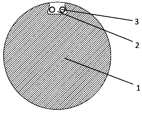
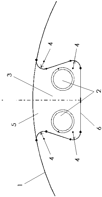
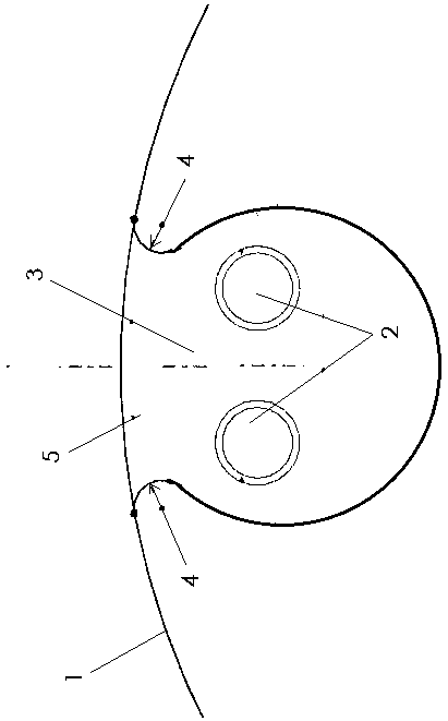
[0027] The intelligent well testing steel wire for distributed optical fiber detection of the present invention comprises a steel wire main body 1, an optical fiber unit 2 and a sealant 3, the steel wire main body is a steel wire with a groove; the optical fiber unit is located in the groove of the steel wire, and the groove is filled with Sealant, the optical fiber unit is fixed in the groove by the sealant; the maximum inner width of the groove of the steel wire body is greater than the width of the opening.

[0028] The optical fiber unit is composed of a single or multiple detection optical fibers laid in a mosaic type.

[0029] The diameter of the steel wire main body is 2-5mm. Specifically, 2.0mm, 2.3mm, 2.5mm, 2.8mm, 3.0mm, 3.4mm, 3.8mm, 4.0mm, 4.3mm, 4.7mm or 5.0mm can be used.

[0030] The sealant is a temperature-resistant, oil-resistant and pressure-bearing sealant.

[0031] ...


PUM

PropertyMeasurementUnit
Diameteraaaaaaaaaa
Diameteraaaaaaaaaa
Bottom widthaaaaaaaaaa

Abstract

The invention discloses an intelligent well testing wire for a distributive optical fiber detection. The intelligent well testing wire comprises a steel wire body, an optical fiber unit and sealing adhesives; the steel wire body is a steel wire provided with a groove; the optical fiber unit is located in the groove of the steel wire; the groove is filled with the sealing adhesives; the optical fiber unit is fixed in the groove by the sealing adhesives; and the internal maximum width of the groove of the steel wire body is larger than the width of an opening. The intelligent well testing wire has the beneficial effects that under-well data can be acquired in real time by the intelligent well testing steel wire; the intelligent well testing wire can not only be used for descending length correction of the steel wire, but also can be used for acquiring under-well tension, well deviation and shocking data. The optical fiber unit can used for transmitting data in real time, so that duplex communication is realized; under-well pressure, flow and other well testing data are transmitted in real time; the intelligent well testing wire can also serve as a distributive sensor for sound wave/vibration and temperature; the full-thread environment parameters of the steel wire are monitored; a conventional well testing instrument is replaced, and distributive physical parameters which are difficult to monitor in the prior art are provided; and the purchasing cost of the well testing instrument and equipment is greatly lowered.

Description

technical field [0001] The invention relates to the field of well test steel wires in the petroleum industry, in particular to an intelligent well test steel wire for distributed optical fiber detection. Background technique [0002] So far, the function of well testing steel wire is relatively simple, and its main function is to transport downhole tools during oil and water well testing, and complete measurement and fishing work. Under the action of the steel wire's own weight and the weight of the instrument, the steel wire produces plastic deformation during the downhole process, resulting in inaccurate depth calibration of the steel wire, which largely depends on the experience of the operator and the effective design of the tool, and cannot be real-time according to the downhole situation. Take measures; in addition, the application of distributed and discrete optical fiber sensing in oil and gas field development has gradually received more attention and has increasing...

Claims


Application Information

Patent Timeline
IPC IPC(8): E21B47/00E21B47/07E21B47/14E21B47/022E21B33/12G01D21/02
CPCE21B33/1204E21B47/00E21B47/022E21B47/14G01D21/02
Inventor 季昌芸江少帅李元清聂泳培徐晓峰姜再鹏
Owner 山东希尔电缆有限公司
Why Eureka
Try Eureka