An auxiliary device for controlling the height of a gas stove by switching on and off the gas

A gas stove and gas technology, applied in lighting and heating equipment, applications, household stoves, etc., can solve the problems of shortened service life, inconvenient operation, food contamination, etc., achieve high practicability, convenient operation, and increase the use space Effect

Active Publication Date: 2021-07-16
洪怀
View PDF0 Cites 0 Cited by
  • Summary
  • Abstract
  • Description
  • Claims
  • Application Information

AI Technical Summary

Problems solved by technology

[0003] Gas stoves are kitchen utensils that are directly heated by gaseous fuels such as liquefied petroleum gas (liquid), artificial gas, and natural gas. The traditional heating method uses earthen stoves as consoles and firewood as fuel. It is more convenient, the space is tidy and easy to clean up, and it occupies a small space. When modern houses are built, the kitchen area is generally small. The existing gas stove is also directly installed on the table. When not in use, the gas stove occupies The certain position of the table reduces the area where items can be placed. If it cannot be placed, it may be placed near the kitchen, which is very inconvenient to operate, or the items are stacked, for example, when more preparations are required. When serving dishes, you may choose to place the plates containing the dishes on top of the three plates to save space, but there is a certain risk that the upper plates are prone to fall, making the food dirty or even scratching your hands when cleaning up, and burning gas. If the stove is placed directly on the table, water will often splash on the gas stove, which will aggravate the aging of the gas stove and shorten its service life

Method used


Image

  • An auxiliary device for controlling the height of a gas stove by switching on and off the gas
  • An auxiliary device for controlling the height of a gas stove by switching on and off the gas
  • An auxiliary device for controlling the height of a gas stove by switching on and off the gas

Examples


Embodiment Construction

[0025] The following will clearly and completely describe the technical solutions in the embodiments of the present invention with reference to the accompanying drawings in the embodiments of the present invention. Obviously, the described embodiments are only some, not all, embodiments of the present invention. Based on the embodiments of the present invention, all other embodiments obtained by persons of ordinary skill in the art without making creative efforts belong to the protection scope of the present invention.

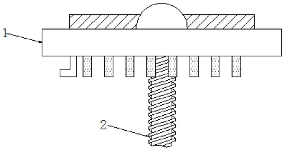
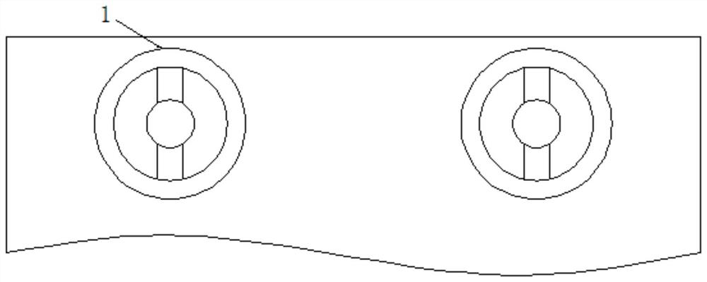
[0026] see Figure 1-9 , an auxiliary device for controlling the height of a gas cooker by switching on and off gas, including a rotary knob 1, and a dial is provided on the outside of the rotary knob 1. When the rotary knob 1 is turned slightly, it is not enough to start a fire, and the continuous rotation of the rotary knob 1 can start a fire and Adjust the size of the firepower. When turning the knob 1 clockwise, the firepower grades are small, medium, larg...


PUM


Abstract

The invention relates to the field of new mechanical technology, and discloses an auxiliary device for controlling the height of a gas stove by switching on and off gas, including a rotary knob, the bottom of which is movably connected with a movable rod; the rotation of the rotary knob causes the second gear bar to go down When the first gear rod moves up, the gas stove also moves up synchronously. When the third gear continues to rotate in the same direction, the positions of the first gear rod and the second gear rod remain unchanged, and the gas cooker can be retracted by turning the knob in the opposite direction. , the gas stove can be raised and lowered by using any burner, and when the gas stove moves to the top of the stove, adjusting the firepower will not affect the position of the stove, which has high practicability. The first gear rod moves down to make the cover The plate moves to the outside of the gas stove, so that the gas stove can move up smoothly, the gas stove returns to the stove, the cover plate moves to the top of the gas stove again to cover it, and the gas stove can be retracted when it is not in use. Increase the use space of the kitchen and make the operation more convenient.

Description

technical field [0001] The invention relates to the technical field of new machinery, in particular to an auxiliary device for controlling the height of a gas stove by switching on and off the gas. Background technique [0002] With the development of science and technology, mechanical equipment is constantly being innovated, which not only plays a major role in industrial production, but also brings convenience to people's lives. [0003] Gas stoves are kitchen utensils that are directly heated by gaseous fuels such as liquefied petroleum gas (liquid), artificial gas, and natural gas. The traditional heating method uses earthen stoves as consoles and firewood as fuel. It is more convenient, the space is tidy and easy to clean up, and it occupies a small space. When modern houses are built, the kitchen area is generally small. The existing gas stove is also directly installed on the table. When not in use, the gas stove occupies The certain position of the table reduces the...

Claims


Application Information

Patent Timeline
Patent Type & Authority Patents(China)
IPC IPC(8): F24C3/12F24C15/08
CPCF24C3/126F24C15/086
Inventor 洪怀
Owner 洪怀
Why Eureka
Try Eureka