Structured light plane calibration method and system in railway foreign matter detection scene

A technology of foreign matter detection and light plane, which is applied in the field of detection and inspection, can solve the problem of low efficiency of railway foreign matter intrusion detection, achieve the effect of reducing cumulative errors and expanding the detection area

Inactive Publication Date: 2020-03-27
CENT SOUTH UNIV +1
View PDF4 Cites 6 Cited by
  • Summary
  • Abstract
  • Description
  • Claims
  • Application Information

AI Technical Summary

Problems solved by technology

[0004] The purpose of the present invention is to provide a structured light optical plane calibration method and its system in the scene of railway f

Method used


Image

  • Structured light plane calibration method and system in railway foreign matter detection scene
  • Structured light plane calibration method and system in railway foreign matter detection scene
  • Structured light plane calibration method and system in railway foreign matter detection scene

Examples


Embodiment 1

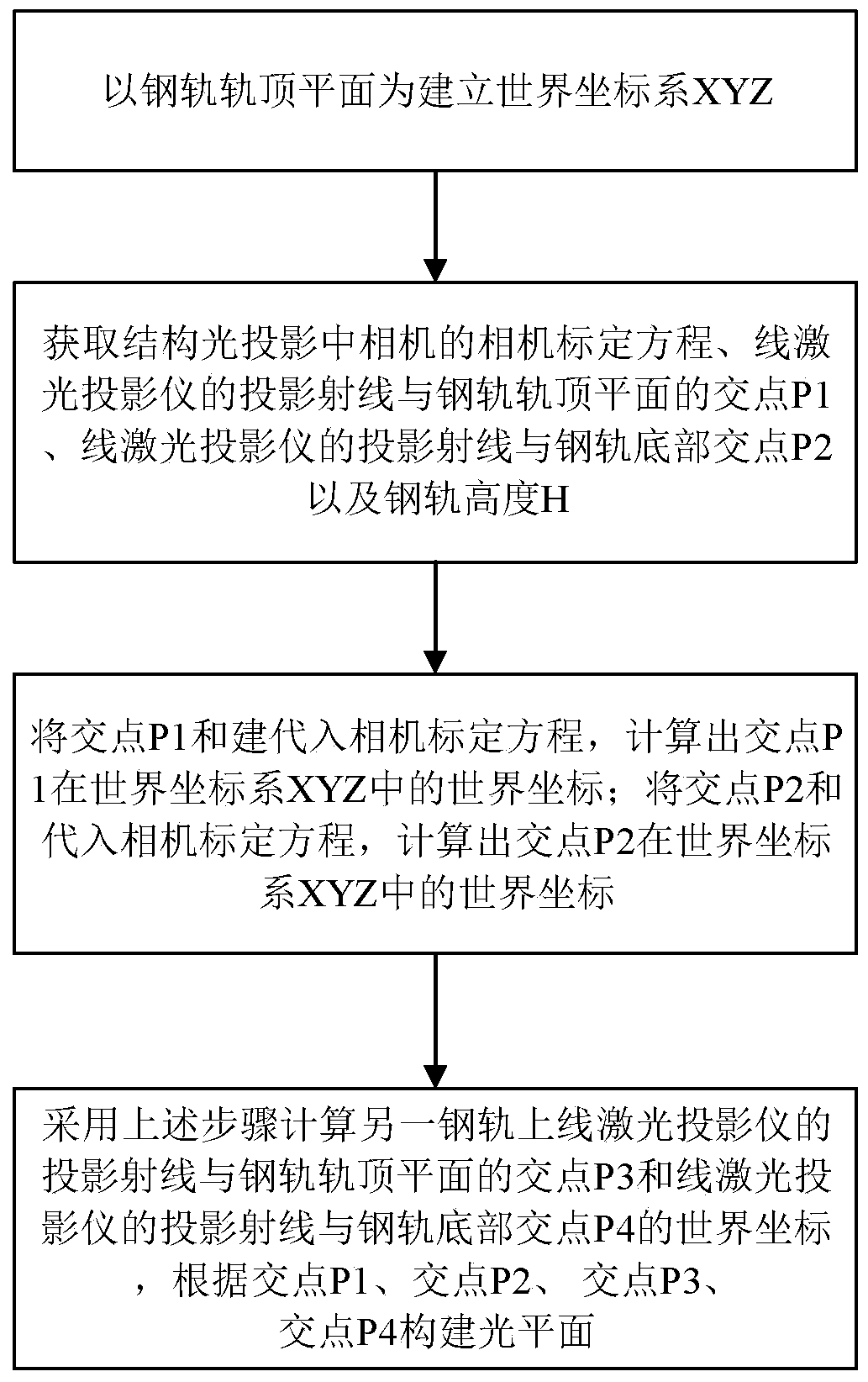
[0032] This embodiment provides a structured light plane calibration method in the railway foreign object detection scene, see figure 1 and image 3 , including the following steps:

[0033] S1: Establish the world coordinate system XYZ with the top plane of the rail as Z=0.

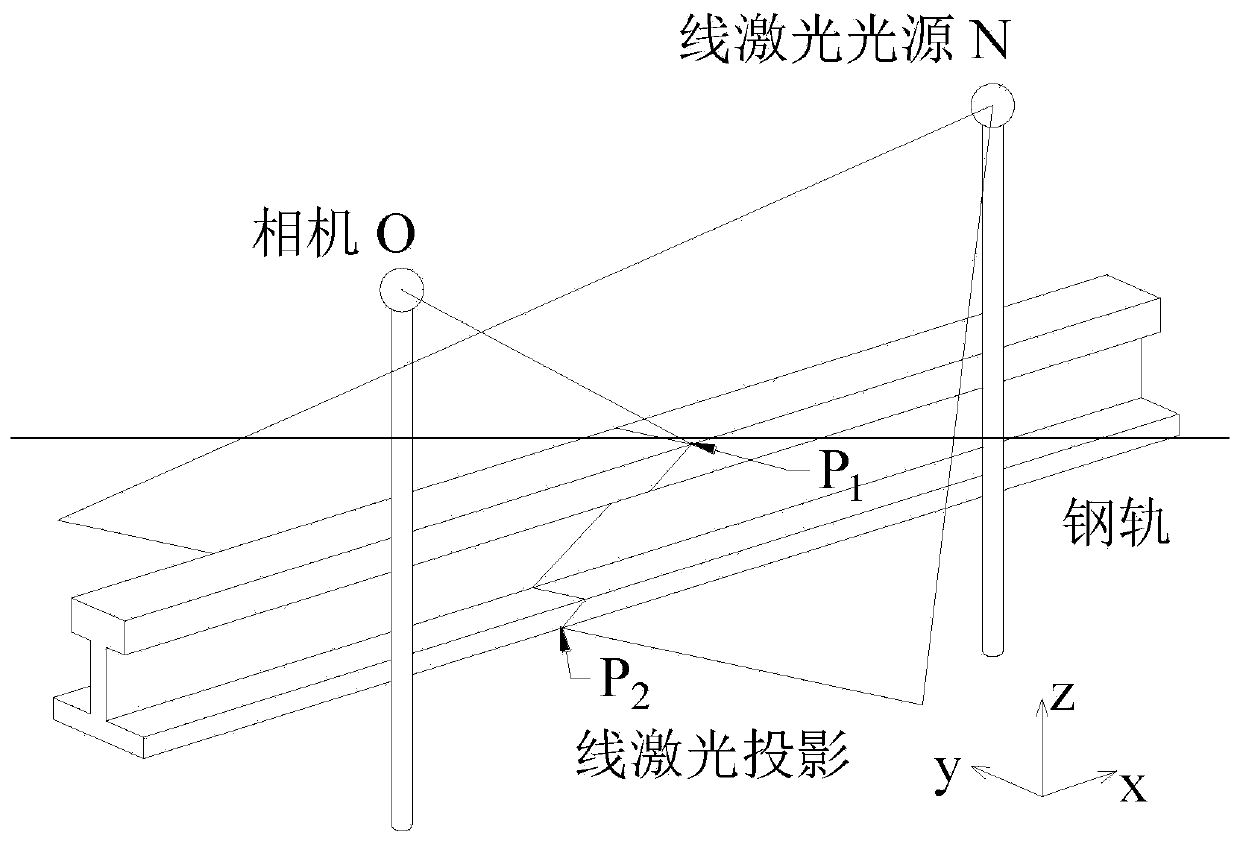
[0034] S2: Obtain the camera calibration equation of the camera in the structured light projection, the intersection point P1 of the projection ray of the line laser projector and the rail top plane Z=0, the intersection P2 of the projection ray of the line laser projector and the bottom of the rail, and the height H of the rail.

[0035] Structured light is a set of system structures composed of projectors and cameras. The specific light information is projected onto the surface of the object and the background by the projector, and then collected by the camera. According to the change of the light signal caused by the object, the information such as the position and depth of the object is calculated...

Embodiment 2

[0052] Write a program to achieve optical plane calibration. According to the procedure in Embodiment 1, the light plane calibration program should include four functional modules: camera calibration, target point extraction, target point world coordinate calculation, and light plane equation calculation.

[0053] Camera calibration determines the coordinate system transformation relationship. Use the Camera Calibrator in the Matlab toolbox to calibrate the camera. Target point extraction is realized by image difference and template matching. Firstly, images are taken under the condition of on and off of the line laser projector, and the line laser projection is obtained by difference of the gray value of the image. Then use the method of template matching to determine the Z coordinate of the target point. Calculate the world coordinates of the target point according to the Z coordinate, pixel coordinate and camera calibration equation of the target point. Calculate the op...


PUM


Abstract

The invention discloses a structured light plane calibration method and system in a railway foreign matter detection scene. The method comprises the following steps: establishing a world coordinate system XYZ by taking a steel rail top plane as Z = 0; obtaining a camera calibration equation of a camera in structured light projection, an intersection point P1 of projection rays of a line laser projector and a steel rail top plane Z = 0, an intersection point P2 of projection rays of the line laser projector and the bottom of the steel rail and the height H of the steel rail; substituting the intersection point P1 and Z = 0 into a camera calibration equation, and calculating world coordinates of the intersection point P1 in a world coordinate system XYZ; substituting the intersection point P2 and Z =-H into a camera calibration equation, and calculating world coordinates of the intersection point P2 in a world coordinate system XYZ; and calculating the world coordinates of the intersection point P3 of the projection ray of the linear laser projector on the other steel rail and the steel rail top plane Z = 0 and the intersection point P4 of the projection ray of the linear laser projector and the steel rail bottom by adopting the steps, and constructing a light plane according to P1, P2, P3 and P4.

Description

technical field [0001] The invention relates to the field of detection and inspection, and specifically discloses a structured light plane calibration method and a system thereof in a railway foreign object detection scene. Background technique [0002] The incident of foreign matter intrusion into railway lines is sudden, unpredictable, and destructive. It will seriously threaten traffic safety, disrupt the normal order of railway transportation, cause huge losses of people's lives and property, and affect social stability. Timely detection of foreign objects on railways and elimination of hidden dangers can effectively reduce the risk of traffic accidents caused by foreign object intrusion. [0003] Most of the existing foreign object intrusions rely on image acquisition devices along the railway to collect images, and judge whether there is foreign object intrusion on the railway based on machine vision. However, it is greatly affected by the environment, the detection e...

Claims


Application Information

Patent Timeline
IPC IPC(8): G01B11/25G01C11/00G01C11/30
CPCG01B11/2504G01B11/2545G01C11/00G01C11/30
Inventor 鲁寨军石先明崔灿刘立海梁习锋王超东刘应龙王耀国周伟
Owner CENT SOUTH UNIV
Why Eureka
Try Eureka