
Bridge rope detection equipment

A detection equipment and rope technology, applied in the field of logistics sorting equipment, can solve the problems of low detection efficiency, waste of time for measurement and detection, and danger, etc., and achieve the effect of simple equipment structure, good safety, and good resistance to bad weather

Inactive Publication Date: 2020-03-27
杭州伍月装饰设计有限公司
View PDF0 Cites 0 Cited by
  • Summary
  • Abstract
  • Description
  • Claims
  • Application Information

AI Technical Summary

Problems solved by technology

[0002] Bridge ropes often use steel rope structures to suspend the bridge deck and bridge piers. The existing bridge rope detection methods often use manual detection. This method is not only dangerous, but also has extremely low detection efficiency, which is very unfavorable for batch detection. At the same time, because the detection process will be affected by harsh conditions such as strong wind and heavy rain, it will make the equipment and personnel unable to perform efficient measurement, which will not only waste a lot of time for measurement and detection, but also reduce the safety factor of equipment and personnel. Some testing equipment monitors and shoots the rope by suspending in the air, which is very unfavorable for observation and measurement in heavy wind and heavy rain, which reduces the continuous working ability of the equipment and is very unfavorable for large-scale testing and promotion

Method used


Image

  • Bridge rope detection equipment
  • Bridge rope detection equipment
  • Bridge rope detection equipment

Examples


Embodiment Construction

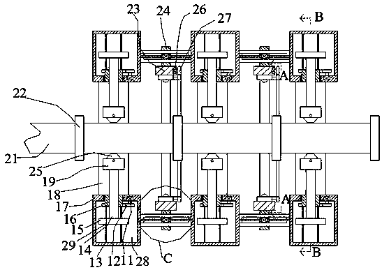
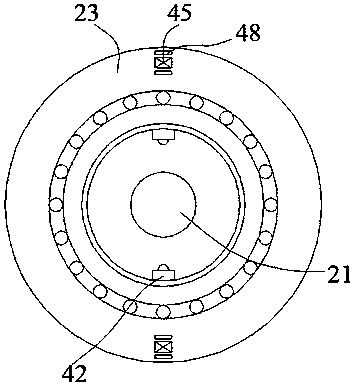
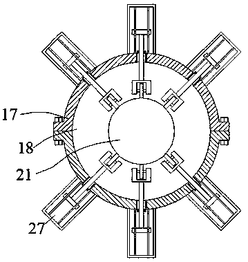
[0020] Such as Figure 1-Figure 4 As shown, the present invention is described in detail. For the convenience of description, the orientations mentioned below are now stipulated as follows: figure 1 The up, down, left, right, front and back directions of the projection relationship itself are consistent. A bridge rope detection device of the present invention includes a plurality of fixed rings 23. The fixed rings 23 are annular structures, and an inner ring 44 is arranged for rotation in the fixed ring 23. The inner ring 44 is provided with a ring cavity 43 penetrating left and right, the inner wall of the ring cavity 43 is provided with a plurality of cameras 42, the right end surface of the inner ring 44 is fixed with a toothed ring 40, and the toothed ring 40 is provided with The inner cavity 41 of the toothed ring penetrates, and the right end surface of the fixed ring 23 is fixed with a side drive motor 26, and a transmission gear 27 is provided for power connection on o...


PUM


Abstract

The invention discloses bridge rope detection equipment. The bridge rope detection equipment comprises a plurality of fixing rings, and the fixing ring is of an annular structure. An inner ring is rotationally arranged in the fixed ring, a ring inner cavity penetrating left and right is formed in the inner ring, a plurality of cameras are arranged on the inner wall of the annular inner cavity, a gear ring is fixedly arranged on the right end surface of the inner ring, a through gear ring inner cavity is formed in the gear ring, a side driving motor is fixedly arranged in the right end surfaceof the fixed ring, a transmission gear is arranged on one side of the side driving motor in a power connection manner, the transmission gear is meshed with the gear ring, and a rope is arranged in thefixing ring. The equipment is simple in structure, by the adoption of the clamping detection device and the moving device, and the rope can be detected and shot in an all-around mode through the equipment; and meanwhile, by means of the structure of the equipment, the function of resisting severe weather is achieved while the requirement for equipment moving is met, and due to the fact that the equipment does not need to be carried to the bridge rope by people, good safety is achieved.

Description

technical field [0001] The invention relates to the technical field of logistics sorting equipment, in particular to bridge rope detection equipment. Background technique [0002] Bridge ropes often use steel rope structures to suspend the bridge deck and bridge piers. The existing bridge rope detection methods often use manual detection. This method is not only dangerous, but also has extremely low detection efficiency, which is very unfavorable for batch detection. At the same time, because the detection process will be affected by harsh conditions such as strong wind and heavy rain, it will make the equipment and personnel unable to perform efficient measurement, which will not only waste a lot of time for measurement and detection, but also reduce the safety factor of equipment and personnel. Some testing equipment monitors and shoots the rope by floating in the air, which is very unfavorable for observation and measurement in heavy wind and heavy rain, which reduces the...

Claims


Application Information

Patent Timeline
IPC IPC(8): G01N21/952G01N21/01
CPCG01N21/01G01N21/952G01N2021/0112
Inventor 不公告发明人
Owner 杭州伍月装饰设计有限公司
Learn More