
Rotating plate unit and production method thereof

A technology of rotating disk and rotor, which is applied in the manufacture of rotating disk units, and in the field of manufacturing such rotating disk units, to achieve the effect of reducing costs

Pending Publication Date: 2020-03-27
ROBERT BOSCH GMBH
View PDF0 Cites 0 Cited by
  • Summary
  • Abstract
  • Description
  • Claims
  • Application Information

AI Technical Summary

Problems solved by technology

Therefore, the compact integration of multiple non-contact transfer elements into a rotating disk unit is a technical challenge for high rotation speeds (>600 rpm)

Method used


Image

  • Rotating plate unit and production method thereof
  • Rotating plate unit and production method thereof
  • Rotating plate unit and production method thereof

Examples


Embodiment Construction

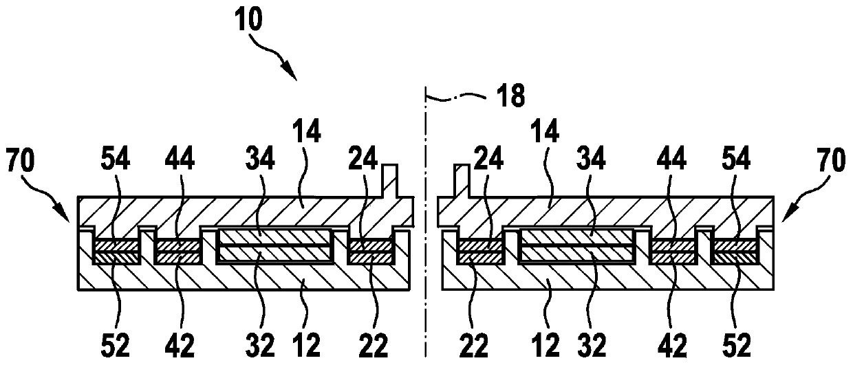
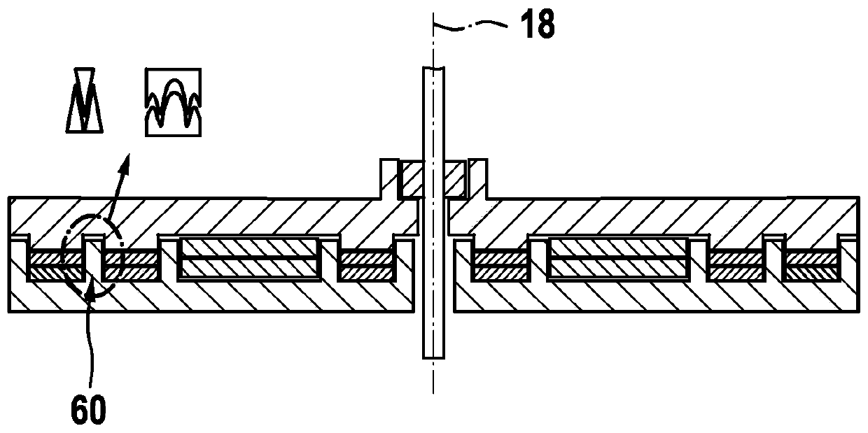
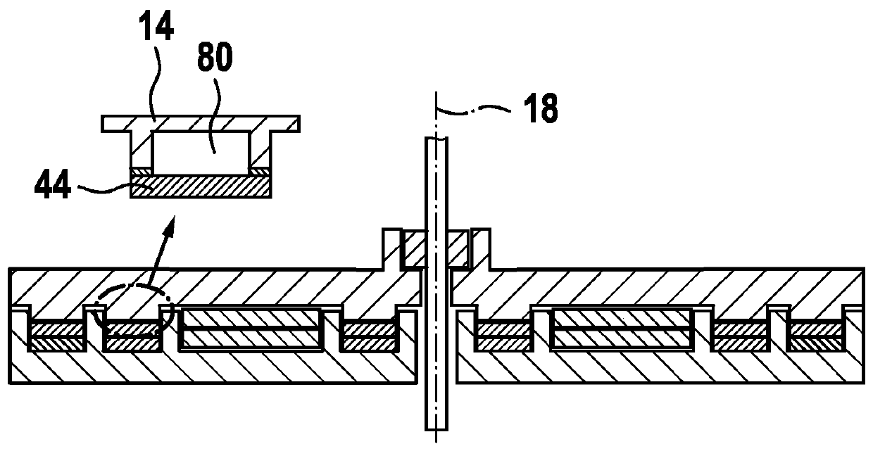
[0035] figure 1 A schematic diagram of a rotating disk unit 10 according to the present invention is shown. The illustrated rotating disk unit 10 includes a disk-shaped stator 12 and a disk-shaped rotor 14, wherein the disk-shaped surfaces of the stator 12 and the rotor 14 are arranged parallel to each other and spaced apart from each other along a central axis 18; and the rotating disk unit comprises a non-contact transmission system between the stator 12 and the rotor 14, the transmission system having a plurality of pairs of transmission elements 22,24; 32,34; 42,44; 52,54 corresponding to each other, wherein each Each pair of first transmission elements 22, 32, 42, 52 is respectively arranged on the surface of the stator 12 facing the rotor 14 and each pair of corresponding second transmission elements 24, 34, 44, 54 is arranged on the surface of the rotor 14 facing 32 , 34 ; 42 , 44 ; 52 , 54 of each pair corresponding to each other at a distance from each other at least...


PUM


Abstract

The invention relates to a rotating plate unit and a production method thereof. The rotating plate unit for a lidar device includes a disk-shaped stator and disk-shaped rotor with respective disk-shaped surfaces that are parallel to and at a distance from each other along a central axis; and a contactless transmission system between the stator and the rotor, which has pairs of mutually corresponding transmission elements, a first transmission element of a respective pair being situated on the surface of the stator facing the rotor and the associated second transmission element of the respective pair in each case being situated on the surface of the rotor facing the stator, the mutually corresponding transmission elements of a pair being at least sectionally situated at a distance and across from each other during a rotation of the rotor; the pairs of individual transmission elements of the transmission system being situated in spatial separation from one another along the radius of therotating plate unit.

Description

technical field [0001] The invention relates to a rotary disk unit and a method for manufacturing a rotary disk unit. In particular, the invention relates to a rotary disk unit with a contactless transfer system between a stator and a rotor for a LiDAR device and a method for producing such a rotary disk unit. Background technique [0002] LiDAR devices will pioneer applications in enabling autonomous driving functions over the next few years. In order to cover large horizontal sensing angles between 150° and 360°, currently only mechanical laser scanners are known. In a first configuration, only the motor-driven deflection mirror rotates in a rotating mirror laser scanner whose maximum sensing range is limited to approximately 150°. For larger sensing ranges up to 360°, all electro-optical components are located on a motor-driven rotating disk or rotor. Most of the other electronic components are arranged on the corresponding stator. Here, the stator and the rotor toget...

Claims


Application Information

Patent Timeline
Patent Type & Authority Applications(China)
IPC IPC(8): G01S17/931G01S7/481
CPCG01S7/4817H02K11/21H02K11/35H02K15/02G01S7/4813G01S7/4815G08C17/00H01F27/36H01F27/363H01F38/14H01F38/18H01F41/00H02J50/10
Inventor A·格赖纳
Owner ROBERT BOSCH GMBH
Learn More