
Topological graph conversion system and method

A conversion method and conversion system technology, applied in the direction of resource allocation, program control design, instruments, etc., can solve the problems of software programming work callback trap, unable to show the advantages of automatic parallelism of the data flow engine, etc., to improve computing utilization, eliminate Data processing waiting and delay, the effect of eliminating the waiting process

Active Publication Date: 2020-03-27
BEIJING ONEFLOW TECH CO LTD
View PDF7 Cites 5 Cited by
  • Summary
  • Abstract
  • Description
  • Claims
  • Application Information

AI Technical Summary

Problems solved by technology

The result of this is that because these operations are not encoded in the data flow diagram, the advantages of automatic parallelism of the data flow engine cannot be shown, and the software programming work will fall into the so-called callback trap during synchronous programming.

Method used


Image

  • Topological graph conversion system and method
  • Topological graph conversion system and method
  • Topological graph conversion system and method

Examples


Embodiment Construction

[0033] The present invention will be described in further detail below in conjunction with the embodiments and accompanying drawings, so that those skilled in the art can implement it with reference to the description.

[0034] Reference will now be made in detail to the exemplary embodiments, examples of which are illustrated in the accompanying drawings. When the following description refers to the accompanying drawings, the same numerals in different drawings refer to the same or similar elements unless otherwise indicated. The implementations described in the following exemplary examples do not represent all implementations consistent with the present disclosure. Rather, they are merely examples of apparatuses and methods consistent with aspects of the present disclosure as recited in the appended claims.

[0035] The terminology used in the present disclosure is for the purpose of describing particular embodiments only and is not intended to limit the present disclosure....


PUM


Abstract

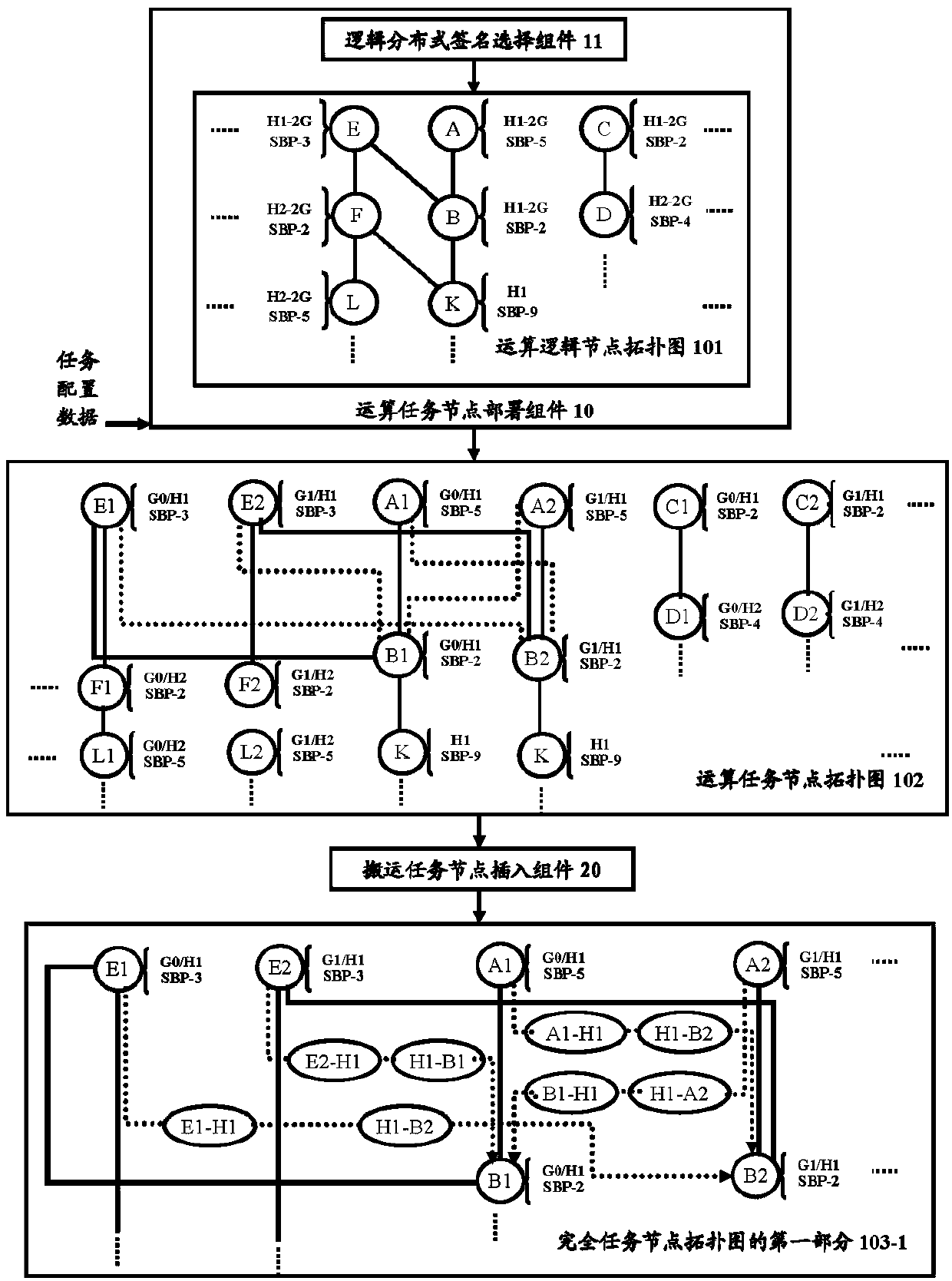
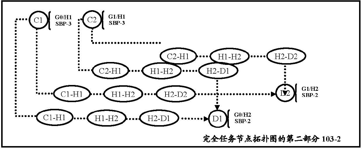
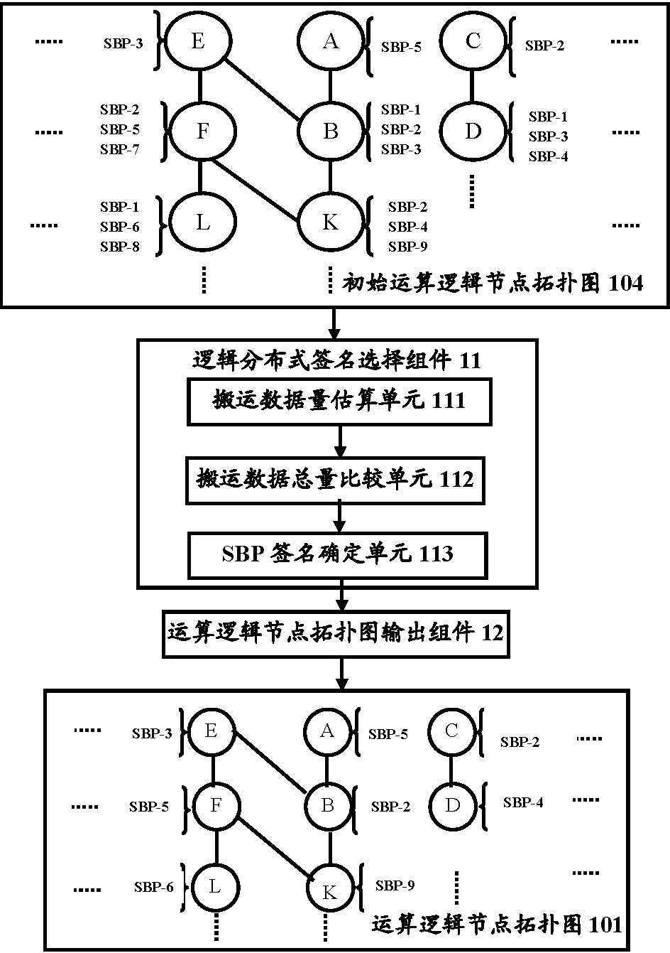
The invention discloses a method for converting an arithmetic logic node topological graph into a task node topological graph. The method comprises the steps of deploying components through operationtask nodes; based on task configuration data in task description input by a user on the basis of given computing resources, fragmenting the task of any arithmetic logic node in the arithmetic logic node topological graph to a specified computing resource so as to generate one or more arithmetic task nodes corresponding to each arithmetic logic node, and endowing each arithmetic task node with a position mark corresponding to the specified computing resource; and inserting the component through the handling task node, when there are different position marks between a first position mark of a first operation task node and a second position mark of a second operation task node serving as an upstream operation task node, one or more carrying task nodes are inserted between the first operationtask node and the second operation task node. Therefore, a complete task node topological graph with the carrying task nodes is obtained.

Description

technical field [0001] The present disclosure relates to a data processing technology. More specifically, the present disclosure relates to a conversion system and a method thereof for converting an operation logic node stack topology graph into a task node topology graph. Background technique [0002] With the popularization of distributed computing, large-scale jobs will deploy different parts of the data to each computing device of different distributed data processing systems for processing through segmentation. In this way, during the processing of a specific job, a The calculation intermediate parameters or results on the computing device will become the input data of the computing task on another computing device, so in order to realize the data synchronization of the intermediate parameters, this will cause the calling overhead of data migration between computing devices. The network communication call is often a bottleneck, and the performance of the network perfor...

Claims


Application Information

Patent Timeline
Patent Type & Authority Applications(China)
IPC IPC(8): G06F9/50
CPCG06F9/5027G06F9/5072G06F9/542
Inventor 袁进辉柳俊丞牛冲李新奇
Owner BEIJING ONEFLOW TECH CO LTD
Learn More