A quick plug-in energy storage connector

A connector and energy storage technology, which is applied in the direction of connection, two-part connection device, and parts of the connection device. Time-consuming and labor-intensive problems, to achieve the effect of saving wiring space, flexible wiring, easy and convenient plugging and unplugging

Active Publication Date: 2021-06-22
深圳金云充科技有限公司
View PDF0 Cites 0 Cited by
  • Summary
  • Abstract
  • Description
  • Claims
  • Application Information

AI Technical Summary

Problems solved by technology

[0002] Energy storage connectors are widely used in energy storage systems. At present, there are two common energy storage connectors on the market: one is a bolt-connected energy storage connector, which has a strong current-carrying capacity, and the connection part is not easy to fail under the long-term action of current. ; The other is a quick-plug energy storage connector, which is divided into two parts: socket and plug, with interlocking function. The contact area between the pin and the socket is small, the current carrying capacity is weak, and the temperature of the contact rises. It is not suitable for high voltage and high current. The pin and the socket are in contact with the self-elasticity of the reed, and the risk of failure is high; these common energy storage The locking device of the connector usually uses bolts for locking connection, and most of them are external locking structures. The force point of the connector locking device is single, the connection is not reliable, and the connection and installation are time-consuming and laborious, and the wiring is not flexible enough.

Method used


Image

  • A quick plug-in energy storage connector
  • A quick plug-in energy storage connector
  • A quick plug-in energy storage connector

Examples


Embodiment 1

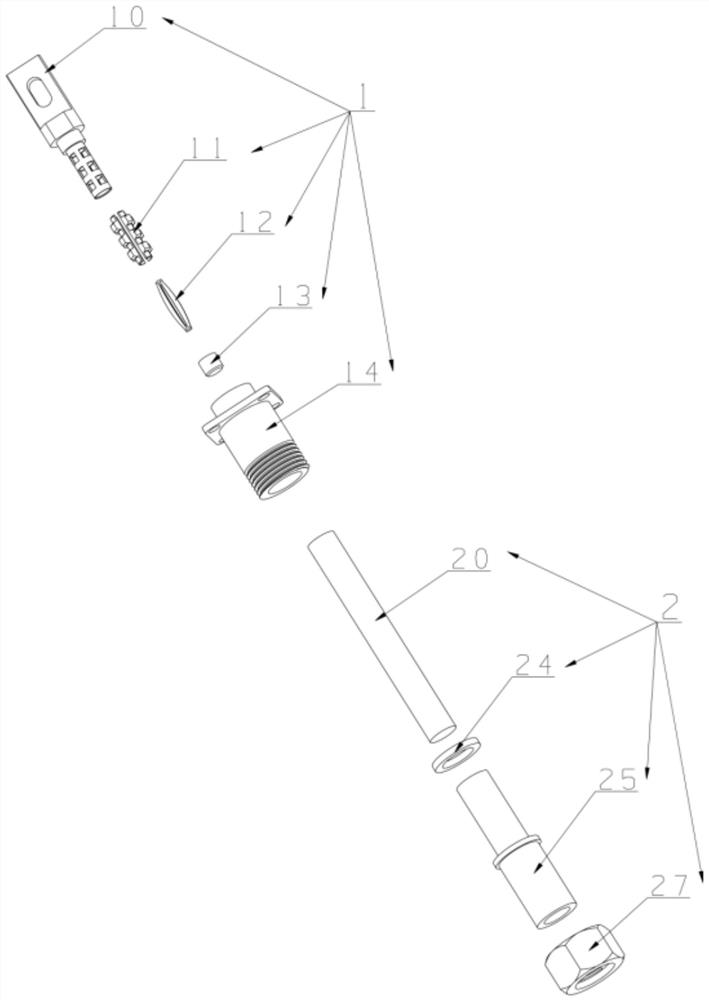
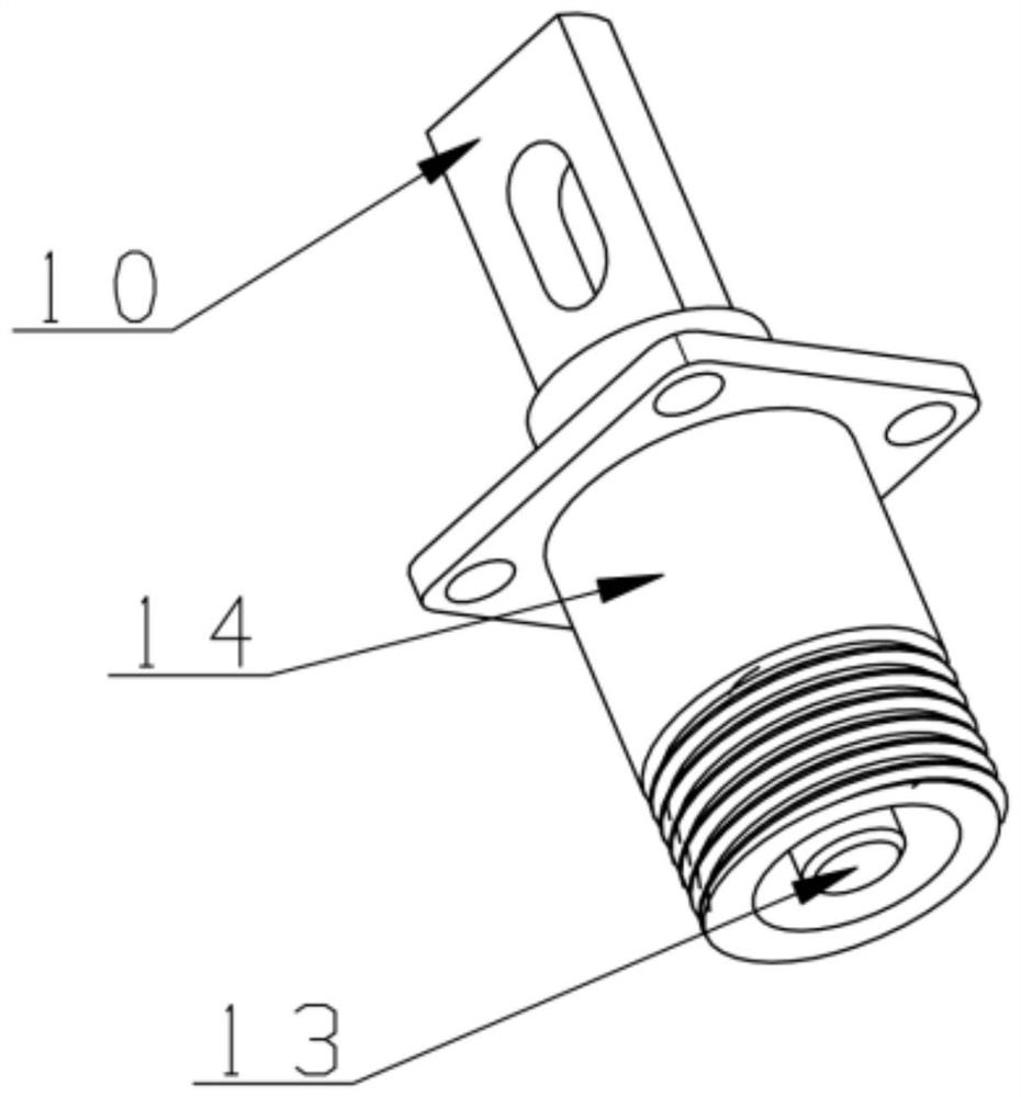
[0031] Such as figure 1 As shown, the quick-plug energy storage connector described in this embodiment includes a socket 1 and a plug 2, and the socket 1 and the plug 2 are connected through a jack 20; The cap 13 and the socket housing 14; the plug 2 includes a jack 20, a sealing ring 24, a plug housing 25 and a locking device.

[0032] Such as figure 1 , 4 , 5, the cylinder of pin 10 is set to be hollow, and the anti-shock cap 13 is fixed on the bottom of the cylinder of pin 10; there are slots on the cylindrical surface, and a plurality of contact pieces 11 are combined in the cylinder of pin 10, The contact piece 11 is provided with protruding contacts, and the contact piece 11 is provided with an elastic piece 12, which is used to spread the contact piece 11, so that the contacts protrude from the slot hole, increasing the contact area between the pin 10 and the socket 20, Greatly improve the current-carrying capacity of the connector and reduce the temperature rise of ...

Embodiment 2

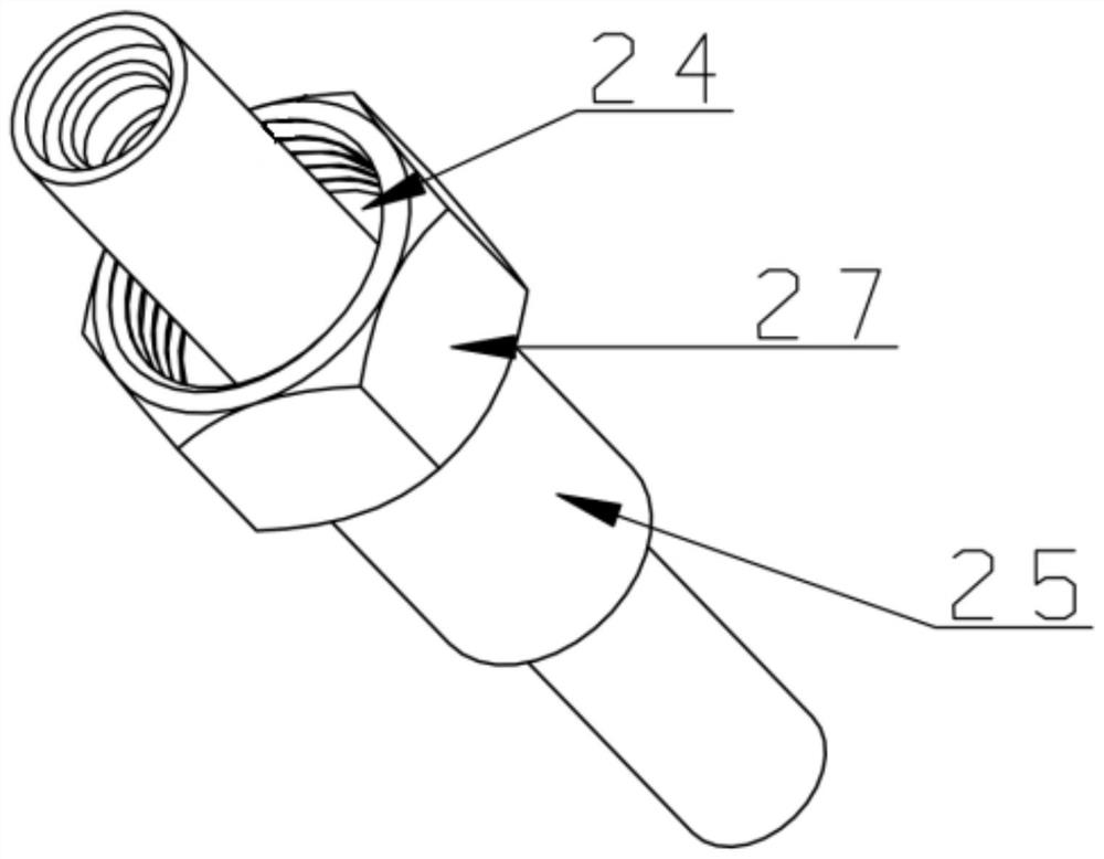
[0037] Such as Figure 7 , 8, 9, and 10, the fast plug-in energy storage connector in this embodiment improves the locking device and the plug housing 25 on the basis of the first embodiment. The locking device in this embodiment includes a locking reed 23, a locking button 21, a ferrule 22 and a socket housing 14. The bottom of the cylinder of the socket housing 14 is provided with an annular chute that matches the locking reed 23. ; The plug housing 25 in the present embodiment is a right-angle shape, including a large round hole, a small round hole and a side round hole, and the inside of the big round hole is set as three steps; There is an annular groove, and a sealing ring 24 is placed in the annular groove; the locking reed 23 is set on the middle step of the large round hole, and the annular plane of the locking reed 23 is located on the top step of the large round hole; the locking button 21 is pressed into the ferrule 22 and put it in the large round hole, so that ...


PUM


Abstract

The invention provides a quick plug-in energy storage connector, which belongs to the technical field of connectors, and mainly includes a socket and a plug. The pins in the socket adopt a hollow cylinder structure with slotted holes. Combined contacts control the contact between the contact and the socket through the expansion and contraction of the shrapnel in the contact, which increases the contact area between the pin and the socket, improves the current carrying capacity of the connector, and reduces the temperature rise of the contacts; the locking device adopts The locking button, the locking reed and the annular chute of the socket shell cooperate with each other, the structure is simple, and after the plug and the socket are mated, the plug can still be rotated 360 degrees, which can be flexibly wired; the other locking device is matched with a threaded nut , the locking device is evenly stressed, and the connection is firm and reliable; there is a sealing ring inside the plug shell to ensure that the connector can be sealed and waterproof.

Description

technical field [0001] The invention belongs to the technical field of connectors, in particular to a quick-plug energy storage connector. Background technique [0002] Energy storage connectors are widely used in energy storage systems. At present, there are two common energy storage connectors on the market: one is a bolt-connected energy storage connector, which has a strong current-carrying capacity, and the connection part is not easy to fail under the long-term action of current. ; The other is a quick-plug energy storage connector, which is divided into two parts: socket and plug, with interlocking function. The contact area between the pin and the socket is small, the current carrying capacity is weak, and the temperature of the contact rises. It is not suitable for high voltage and high current. The pin and the socket are in contact with the self-elasticity of the reed, and the risk of failure is high; these common energy storage The locking device of the connector...

Claims


Application Information

Patent Timeline
Patent Type & Authority Patents(China)
IPC IPC(8): H01R13/17H01R13/622H01R13/627H01R13/633H01R13/52H01R13/46H01R24/00
CPCH01R13/17H01R13/46H01R13/5219H01R13/622H01R13/6277H01R13/633H01R24/00
Inventor 王匀徐磊何培瑜黄灿许桢英万伟超朱义清陈修祥朱长顺朱奕帆
Owner 深圳金云充科技有限公司
Why Eureka
Try Eureka