Static contact and switch cabinet using static contact

A technology of static contacts and contacts, applied in the direction of pull-out switch cabinets, switchgear, switchgear components, etc., can solve the problems of high cost of static contacts, easy to loosen, unable to meet installation conditions, etc., and save materials. Cost, the effect of increasing the conductive area

Active Publication Date: 2020-03-27
HENAN PINGGAO GENERAL ELECTRIC CO LTD +2
View PDF6 Cites 3 Cited by
  • Summary
  • Abstract
  • Description
  • Claims
  • Application Information

AI Technical Summary

Problems solved by technology

[0005] The purpose of the present invention is to provide a static contact to solve the technical problems in the prior art that the single hole installation of the static contact is easy to loose, and the installation of multiple holes causes the high cost of the static contact and cannot meet the installation conditions

Method used


Image

  • Static contact and switch cabinet using static contact
  • Static contact and switch cabinet using static contact
  • Static contact and switch cabinet using static contact

Examples


Embodiment 1

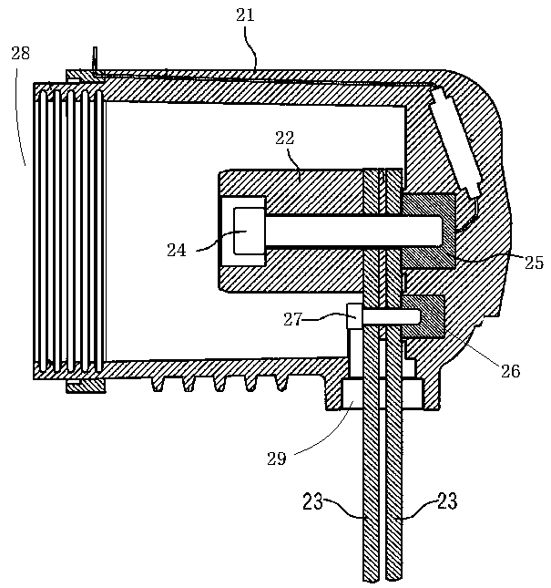
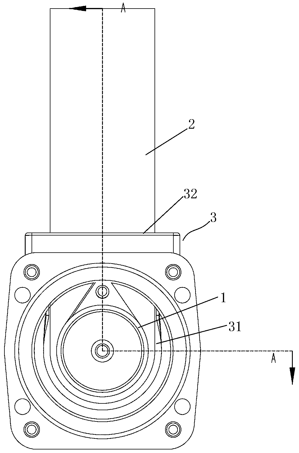
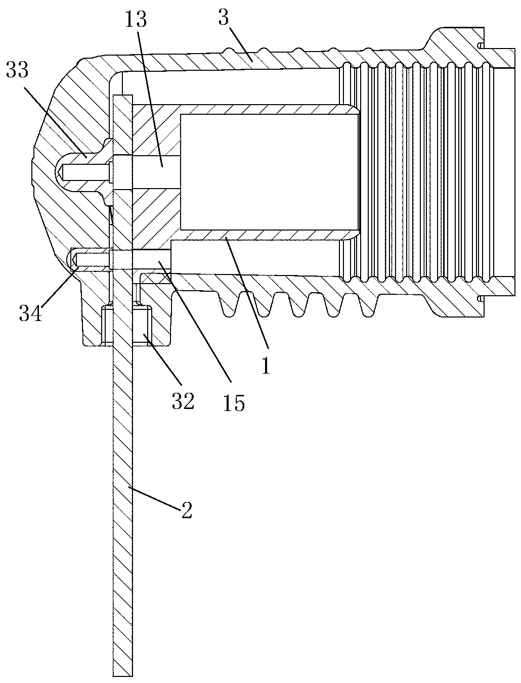
[0043] Specific embodiment 1 of switchgear of the present invention: as Figure 2-9 As shown, the switchgear in this embodiment is a handcart type switchgear, and the switchgear includes a circuit breaker handcart, a static contact 1 , a busbar 2 and a contact box 3 . The static contact 1 is fixed in the contact box 3, the main contact of the circuit breaker trolley can be inserted into the contact box 3, and electrically connected with the static contact 1 in the contact box 3, and one end of the busbar 2 is extended into the The inside of the contact box 3 is conductively connected with the static contact 1 .

[0044] The contact box 3 is an insulating cylinder whose axis extends along the front-to-back direction, and the front end is open and the rear end is closed. The static contact 1 is fixedly installed in the contact box 3; the front opening of the contact box 3 constitutes a circuit breaker hand The main contact of the car is inserted into the contact insertion port ...

Embodiment 2

[0052] Embodiment 2 of the switchgear of the present invention is different from Embodiment 1 in that: the connecting ear plate is welded and fixed to the contact body.

Embodiment 3

[0053] Embodiment 3 of the switchgear of the present invention differs from Embodiment 1 in that the shape of the connecting ear plate is semicircular; in other embodiments, it may also be oval.

[0054] Embodiment 4 of the switchgear of the present invention is different from Embodiment 1 in that the width of the connecting ear plate from the first end to the second end remains unchanged, and at this time, the dimensions of the inner support plate and the outer support plate can be equal , or the radial size of the inner support plate is larger than the size of the outer support plate.

[0055] In the embodiment of the static contact of the present invention, the structure of the static contact is the same as that of the above-mentioned static contact, and will not be repeated here to avoid repetition.


PUM


Abstract

The invention relates to a static contact and a switch cabinet using the static contact, the switch cabinet comprises the static contact, a contact box and a busbar, the static contact is installed ina static contact cavity, and the rear end surface of the static contact is conductively matched with the surface of the busbar; the contact body is provided with a built-in mounting hole which corresponds to the first connecting hole in the busbar and is provided with a fastener in a penetrating manner; the static contact further comprises a connecting lug plate with a first end and a second end,the first end is connected to the outer peripheral surface of the contact body, and the second end extends in the radial direction of the contact body relative to the first end, so that the second end of the connecting lug plate extends towards the busbar wire inlet when the static contact is mounted in the contact box; the rear side plate surface of the connecting lug plate and the rear end surface of the contact body form a conductive matching surface together, and the conductive matching surface is used for being conductively matched with the surface of the busbar; and the connecting lug plate is provided with an external mounting hole which corresponds to the second connecting hole on the busbar and is penetrated by a fastener. The technical problems that single-hole installation is easy to loosen and multi-hole installation causes high cost of the static contact are solved.

Description

technical field [0001] The invention relates to a static contact and a switchgear using the static contact. Background technique [0002] In the complete set of switchgear equipment, it includes the contact box and the static contact installed in the contact box, and the static contact is conductively connected with the busbar (that is, the copper bar). Specifically, such as the authorized announcement number CN208385840 U The contact box and switchgear for the switchgear disclosed by the Chinese utility model patent, such as figure 1 As shown, the contact box 21 includes a contact box body with a static contact cavity, the static contact 22 is fixedly installed on the bottom of the contact box body, and the front end of the contact box body is used for the main contact insertion and static contact of the handcart. The contact 22 is plugged into the contact insertion port 28 , and the radial side of the contact box body is provided with a bus bar inlet 29 for the bus bar 23...

Claims


Application Information

Patent Timeline
Patent Type & Authority Applications(China)
IPC IPC(8): H02B11/04H02B11/167
CPCH02B11/04H02B11/167
Inventor 任建超李军浩张盼盼赵国辉刘晓焱王焕张二勇杨晓敏汪强郑春阳郭佩淇
Owner HENAN PINGGAO GENERAL ELECTRIC CO LTD
Why Eureka
Try Eureka