[0039] The technical solutions in the embodiments of the present invention will be clearly and completely described below with reference to the accompanying drawings in the embodiments of the present invention. Obviously, the described embodiments are only a part of the embodiments of the present invention, but not all of the embodiments. Based on the embodiments of the present invention, all other embodiments obtained by those of ordinary skill in the art without creative efforts shall fall within the protection scope of the present invention.
[0040] The purpose of the present invention is to provide an intelligent mixer for saving labor costs and improving mixing efficiency.
[0041] In order to make the above objects, features and advantages of the present invention more clearly understood, the present invention will be described in further detail below with reference to the accompanying drawings and specific embodiments.
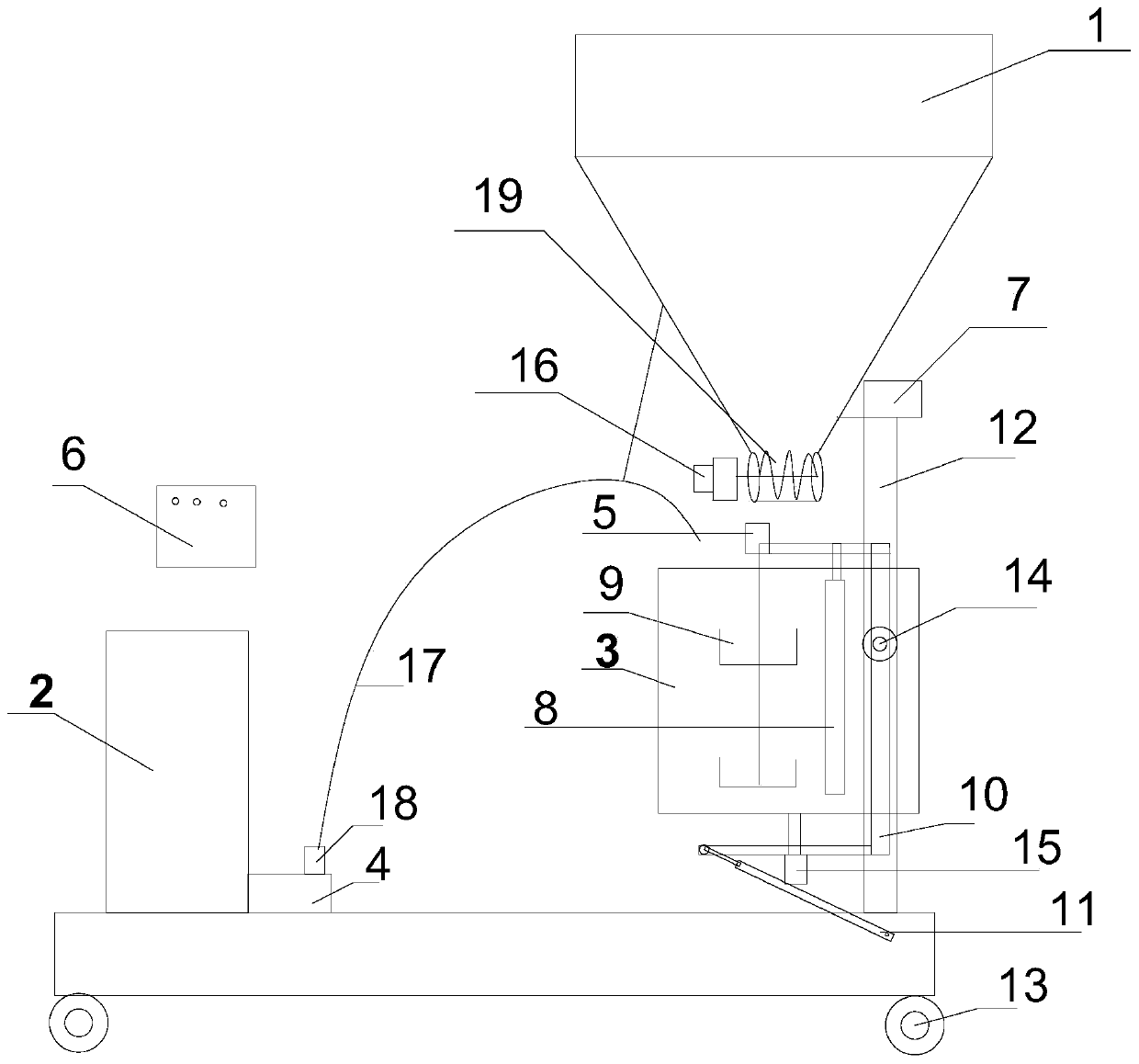
[0042] figure 1 It is a schematic diagram of the structure of the intelligent mixer device of the present invention, such as figure 1 As shown, the intelligent mixer of the present invention includes a main body part, a stirring part and a control unit 6 .
[0043] The main body part specifically includes a main frame 12 , a material tank 1 , a water tank 2 , a water pump 4 , a mixing bucket 3 and an unloading switch.
[0044] The main frame 12 includes a first metal rod, a second metal rod and a third metal rod.
[0045] One end of the first metal rod is vertically connected to one end of the second metal rod, the other end of the second metal rod is vertically connected to one end of the third metal rod, and the first metal rod is connected to the The third metal rod is located on the same side of the second metal rod.
[0046] The main frame 12 further includes a fourth metal rod, a fifth metal rod, a sixth metal rod and a roller 13 .
[0047]The fourth metal rod is placed in parallel with the sixth metal rod, one end of the fourth metal rod is vertically connected to the other end of the first metal rod, and one end of the sixth metal rod is connected to the third metal rod. The other end of the metal rod is vertically connected, the two ends of the fifth metal rod are respectively connected with the midpoint of the fourth metal rod and the midpoint of the sixth metal rod, and the fifth metal rod is connected to the second metal rod. The metal rods are not parallel. Both ends of the fourth metal rod and the sixth metal rod are connected with a roller 13 , and the roller 13 is located below the fourth metal rod and the sixth metal rod.
[0048] The material box 1 is fixedly connected with the second metal rod, and the material box 1 is used for containing cement ash or putty ash.
[0049] The smart mixer of the present invention further includes a vibrator 7, which is in contact with the material box 1, and the vibrator 7 is electrically connected to the controller, and the controller controls the vibrator 7 to vibrate to accelerate Feeding speed.
[0050] The water tank 2 is fixedly connected with the first metal rod, and the water tank 2 is used to hold water or glue.
[0051] The water pump 4 is connected to the water tank 2 , and the water pump 4 is used for pumping water or glue in the water tank 2 .
[0052] The intelligent mixer of the present invention further includes a check valve 18 , and the check valve 18 is arranged at the water outlet of the water pump 4 .
[0053] The mixing barrel 3 is located directly below the material tank 1 and communicates with the water pump 4 . The water pump 4 is communicated with the mixing bucket 3 through a soft water pipe 17 .
[0054] The feeding switch is located at the outlet of the feeding box 1 , and the feeding switch is used to control the feeding of the feeding box 1 .
[0055] The feeding switch includes a third motor 16 and a helical blade 19, the third motor 16 is respectively connected with the controller and the helical blade 19, and the helical blade 19 is arranged at the outlet of the material box 1
[0056] The stirring part includes a stirring frame 10 , a first motor 5 , a stirring rod 9 , a stirring plate 8 , a second electrode and a push rod motor 11 .
[0057] The stirring frame 10 includes a first stirring rod, a second stirring rod and a third stirring rod.
[0058] One end of the first stirring rod is vertically connected to one end of the second stirring rod, the other end of the second stirring rod is vertically connected to one end of the third stirring rod, and the first stirring rod is vertically connected to the The third stirring rod is located on the same side of the second stirring rod, and the second stirring rod is placed in parallel with the first metal rod, and the center of the second stirring rod is the same as the center of the first metal rod The positions are connected by bearings 14 , and the second stirring rod is fixedly connected to the side surface of the stirring barrel 3 .
[0059] The first motor 5 is fixed on the second stirring rod.
[0060] The stirring rod 9 is connected to the shaft of the first motor 5 and is located in the mixing barrel 3 , and the stirring rod 9 is used for stirring cement ash or putty ash in the mixing barrel 3 .
[0061] The stirring plate 8 is located in the stirring barrel 3 and is connected with the first stirring rod.
[0062] The second motor 15 is fixed on the third stirring rod, and the shaft of the second motor 15 is connected with the stirring barrel 3 , and the second motor 15 is used to drive the stirring barrel 3 to rotate.
[0063] One end of the push rod motor 11 is connected with the other end of the third stirring rod, the other end of the push rod motor 11 is connected with the other end of the first metal rod, and the push rod motor 11 is used to push The stirring frame 10 drives the stirring barrel 3 to rotate.
[0064] The control unit 6 is respectively electrically connected with the water pump 4, the feeding switch, the first motor 5, the second motor 15 and the push rod motor 11, and the control unit 6 is used to detect all The current value of the first motor 5 is controlled, and the water pump 4 is controlled to add water or glue into the mixing barrel 3 according to the set time, and the amount of material to be discharged by the feeding switch is controlled according to the current value of the first motor. To control the hardness of the material in the mixing barrel, and according to the set time by controlling the rotation of the first motor 5 and the second motor 15 to achieve timing stirring, and control the push rod motor 11 to achieve dumping according to the set time.
[0065] The control unit 6 further includes a controller and a current sensor.
[0066] The current sensor is respectively connected with the first motor 5 and the controller, the current sensor is used to detect the current value of the first motor 5 and compare the detected current value with the set value to output the comparison result .
[0067] The controller is respectively connected with the feeding switch, the water pump 4, the first motor 5, the second motor and the push rod motor 11, and the controller is used for setting time and comparing results according to Control the opening or closing of the feeding switch, the water pump 4 , the first motor 5 , the second electrode and the push rod motor 11 .
[0068] Preferably, the controller is PLC25 (Programmable Logic Controller, programmable logic controller).
[0069] In addition, the smart mixer of the present invention further includes a first relay 20 , a second relay 21 , a third relay 22 , a fourth relay 23 , a fifth relay 24 and a sixth relay 25 .
[0070] The controller is connected to the first motor 5 through the first relay 20 , and the controller is connected to the feed switch through a third relay 22 .
[0071] The controller is connected to the second motor 15 through the second relay 21 , the controller is connected to the water pump 4 through the fourth relay 23 , and the second controller is connected to the water pump 4 through the fifth relay 24 . The push rod motor 11 is connected.
[0072] figure 2 and image 3 It is a schematic diagram of part of the circuit connection of the intelligent mixer of the present invention, combined with figure 2 and image 3 The specific work flow of the intelligent mixer of the present invention is introduced.
[0073] The specific working process of the intelligent mixer of the present invention is as follows:
[0074] like figure 2 and image 3 As shown, the controller is PLC25, wherein the input terminals of PLC25 are X00, X01, X02, and the output terminals of PLC25 are Y00, Y01, Y02, Y03, Y04, Y05, Y06, Y07.
[0075] There are two current sensors, which are a first current sensor and a second current sensor respectively.
[0076] The first current sensor is respectively connected to the input terminal X01 of the PLC25 and the output terminal Y00 of the PLC25, and the second current sensor is respectively connected to the input terminal X02 of the PLC25 and the output terminal Y01 of the PLC25 connect.
[0077] The input terminal X00 of the PLC25 is connected to an external power supply.
[0078] The output terminal Y02 of the PLC 25 is connected to the third relay 22 , and the third relay 22 is connected to the third motor 16 .
[0079] The output terminal Y03 of the PLC 25 is connected to the fifth relay 24 , and the fifth relay 24 is connected to the push rod motor 11 .
[0080] The output terminal Y04 of the PLC 25 is connected to the first relay 20 , and the first relay 20 is connected to the first motor 5 .
[0081] The output terminal Y05 of the PLC 25 is connected to the second relay 21 , and the second relay 21 is connected to the second motor 15 .
[0082] The output terminal Y06 of the PLC 25 is connected to the fourth relay 23 , and the fourth relay 23 is connected to the water pump 4 .
[0083] The output terminal Y07 of the PLC 25 is connected to the sixth relay 25 , and the sixth relay 25 is connected to the vibrator 7 .
[0084] The normally closed contacts of the first current sensor and the second current sensor are both connected to the input of the third relay 22, and the first current sensor and the second current sensor are directly connected through the third relay. The third motor 16 is controlled to be turned on or off. Then, the amount of material to be cut by the cutting switch is controlled.
[0085] Put cement and sand or putty ash into tank 1, and put water or glue into tank 2 before the mixing work starts. After the power is turned on, the input terminal X00 of the PLC25 is turned on, the device starts to start, and enters the first working state. First, the output terminal Y02 of the PLC25 controls the feeding switch to be turned on, and starts feeding the mixing barrel 3 . The output terminal Y06 of the PLC 25 controls the water pump 4 to add water to the mixing tank 3 according to the set time. The output terminal Y07 of the PLC25 controls the vibrator 7 to be turned on to speed up the feeding speed. The output terminal Y04 of the PLC25 controls the forward rotation of the first motor 5 , and the output terminal Y05 of the PLC25 controls the forward rotation of the second motor 15 to start stirring the mixture in the mixing tank 3 . At the same time, the output terminal Y00 of the PLC 25 controls the first current sensor to detect the current value of the first motor 5, compares the detected current value with the set value, outputs different comparison results, and compares the detected current value with the set value. The result is passed to the input terminal X01 of the PLC25.
[0086] When the comparison result shows that the current value detected by the first current sensor reaches the set value, the input terminal X01 of the PLC25 is connected, and at the same time, the PLC25 is disconnected from the first current sensor and connected to the The PLC 25 is connected to the second current sensor, and controls the feeding switch and the vibrator to be turned off to enter the second stirring stage.
[0087] In the second stirring stage, the PLC 25 controls the first motor 5 to rotate forward according to the set time, and the PLC 25 controls the second motor 15 to rotate forward according to the set time. At this time, the PLC 25 controls the The second current sensor detects the current value of the first motor 5, and judges whether the current value of the first motor 5 reaches the set value. If not, the PLC25 continues to control the feeding switch to turn on, according to the set time. Continue to feed. After the feeding is finished, the PLC 25 controls the first motor 5 and the second motor 15 to continue to operate according to the set time, continues to control the second current sensor to detect the current value of the first motor 5, and repeats The above process is performed until the current value of the first motor 5 reaches the set value.
[0088] If the current value of the first motor 5 reaches the set value, the second current sensor sends a signal to the PLC 25, and the PLC 25 controls the first motor 5 and the second motor 15 to stop running, and The second current sensor is controlled to stop the detection of the first motor 5. At this time, the intelligent mixer of the present invention enters the third working stage.
[0089]The third working stage is the pouring stage of the intelligent mixer of the present invention. In this working stage, the PLC 25 controls the operation of the push rod motor 11 , the push rod motor 11 pushes the stirring frame 10 to rotate relative to the main frame 12 , and the stirring frame 10 drives the stirring bucket 3 at the same time. Tilt and pour the mixed cement in the mixing bucket 3 . At the same time, the PLC 25 controls the first motor 5 and the second motor 15 to reverse, and cooperates with the stirring plate 8 to pour out the cement in the mixing bucket 3 . Meanwhile, a pouring time is set in the PLC25, and the PLC25 controls the push rod motor 11, the first motor 5 and the second motor 15 to operate according to the set pouring time. After the set time is reached, the push rod motor 11 returns to its original position, the first motor 5 and the second motor 15 stop running, the intelligent mixer of the present invention is reset to the state before operation, and the whole mixing process ends.
[0090] The various embodiments in this specification are described in a progressive manner, and each embodiment focuses on the differences from other embodiments, and the same and similar parts between the various embodiments can be referred to each other.
[0091] In this paper, specific examples are used to illustrate the principles and implementations of the present invention. The descriptions of the above embodiments are only used to help understand the methods and core ideas of the present invention; meanwhile, for those skilled in the art, according to the present invention There will be changes in the specific implementation and application scope. In conclusion, the contents of this specification should not be construed as limiting the present invention.