Fan guide cylinder positioning device

A positioning device and guide tube technology, applied in the direction of workpiece clamping devices, manufacturing tools, etc., can solve the problems of large product deformation, low efficiency, low concentricity of the guide tube, etc., to avoid damage, uniform force, ensure The effect of roundness

Pending Publication Date: 2020-03-31
浙江科贸智能机电股份有限公司
View PDF0 Cites 1 Cited by
  • Summary
  • Abstract
  • Description
  • Claims
  • Application Information

AI Technical Summary

Problems solved by technology

This solution leads to low concentricity between the top plate and the guide tube, large product deformation and low efficiency
Some guide tubes need to process holes. The existing solution is to make a positioning drill sleeve. The concentricity depends on several positioning columns on the drill sleeve. For example, the gap between the circumference of the positioning columns is small, because the roundness of the guide tube The problem is that it is not suitable to put it into the guide tube. If the gap is large, the coaxiality between the post-processed hole position and the tube body cannot be guaranteed.

Method used


Image

  • Fan guide cylinder positioning device
  • Fan guide cylinder positioning device
  • Fan guide cylinder positioning device

Examples


Embodiment 1

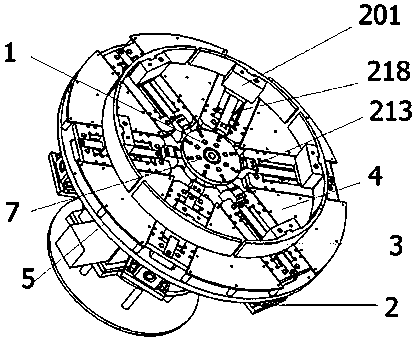
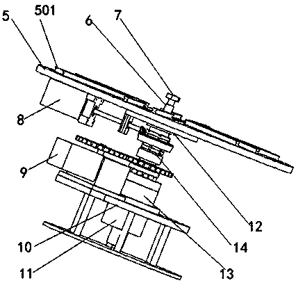
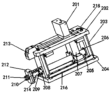
[0029] Such as Figure 1-6 As shown, a positioning device for a fan guide tube mainly includes a main shaft part 14 and a table bottom plate 5. The bottom plate of the table top 5 is a circular plate with 6 mounting holes arranged on the upper surface. The mounting holes extend radially and are evenly arranged around the center of the bottom plate 5 of the table top. A tensioning arc 3 is correspondingly provided on the outside of each mounting hole. All the tensioning arcs 3 are surrounded by circular arcs, and the extension lines of adjacent tensioning arcs are connected to form a tensioning circle. A diameter adjustment mechanism 2 is installed at the position of the installation hole on the bottom plate of the table top 5, and the diameter adjustment mechanism 2 is connected with the tensioning arc 3 in cooperation. The tensioning arc 3 is arc-shaped, and there are projections on the inner wall, and the projections and the slots cooperate to complete the connection betwee...


PUM


Abstract

The invention provides a fan guide cylinder positioning device, which comprises a main shaft component and a table top bottom plate, wherein the main shaft component comprises a main shaft, and the upper end of the main shaft is fixedly connected with the center of the table top bottom plate through a connecting sleeve; the upper surface of the table top bottom plate is provided with n mounting holes, and the mounting holes are uniformly distributed around the center of the table top bottom plate and extend in the radial direction; the outer side of each mounting hole is correspondingly provided with a tensioning arc, and extension lines of the adjacent tensioning arcs are connected to form a tensioning ring in a surrounding manner; the table top bottom plate is provided with diameter adjusting mechanisms at the positions of the mounting holes; each diameter adjusting mechanism comprises a mounting frame and a first motor, and the mounting frame is mounted at the position of the mounting hole and connected with the corresponding tensioning arc in a matched mode; and the first motor drives the mounting frame to slide back and forth along the mounting hole so as to change the inner diameter of the tensioning ring.

Description

technical field [0001] The invention relates to the technical field of fans, in particular to a fan guide tube positioning device. Background technique [0002] In order to improve the performance of the fan, such as air volume, wind pressure, shaft power, noise and vibration, it is one of the most commonly used methods to install a deflector in front of the impeller inlet to change the direction of the airflow. The most commonly used deflector is the deflector cylinder, which is cylindrical and generally consists of an inner cylinder, an outer cylinder, and a deflector plate. In the prior art, the fan deflector cylinder and the top plate are often welded together to form a fan mounting plate. Solve the problem that the top plate of the fan cannot be stretched in one piece and the installation is inconvenient. Existing technology is to drill positioning holes on the guide tube and the top plate, then connect them with bolts, and repair the positioning holes by welding. Thi...

Claims


Application Information

Patent Timeline
Patent Type & Authority Applications(China)
IPC IPC(8): B25B11/00
CPCB25B11/00
Inventor 裘霖富张职锋
Owner 浙江科贸智能机电股份有限公司
Why Eureka
Try Eureka