Control system and control method for bridge installed with viscous damper

A viscous damper and control system technology, applied in the direction of bridges, bridge construction, bridge forms, etc., can solve the problems of affecting durability, large cumulative displacement of beam ends, and easy damage of bridge abutments, so as to improve safety and reliability, Effect of reducing longitudinal cumulative displacement and increasing damping force

Active Publication Date: 2021-10-26
CHINA MAJOR BRIDGE ENERGINEERING
View PDF9 Cites 0 Cited by
  • Summary
  • Abstract
  • Description
  • Claims
  • Application Information

AI Technical Summary

Problems solved by technology

Taking the driving of a car on the main girder as an example, unlike wind load or earthquake load, the driving of a car is a daily behavior, so the longitudinal displacement of the beam end is continuous, that is, there is a vehicle running on the suspension bridge, then the main girder of the suspension bridge will be uninterrupted The longitudinal reciprocating movement of the ground also leads to a large cumulative displacement of the beam end of the main beam
[0003] The hazards of frequent longitudinal reciprocating and large movements of the main girder are mainly manifested in the substantial deterioration of the bearings, expansion joints, and suspension bridge cables, seriously affecting their durability, reducing the service life of the bearings, expansion joints, and suspension bridge cables, and increasing the operation of the suspension bridge. security risk during
[0004] In the prior art, longitudinal limit devices are mostly installed at both ends of the main beam to reduce the maximum displacement of the beam end. However, these longitudinal limit devices have a limited reduction in the cumulative displacement of the beam end. For example, the patent number is ZL201611992980.7 , the authorized invention patent titled "a bridge equipped with a viscous damper", which solves the technical problem that the abutment structure cannot bear the huge tension under the dynamic load, making the abutment easy to damage and poor in structural stability

Method used


Image

  • Control system and control method for bridge installed with viscous damper
  • Control system and control method for bridge installed with viscous damper
  • Control system and control method for bridge installed with viscous damper

Examples


Embodiment

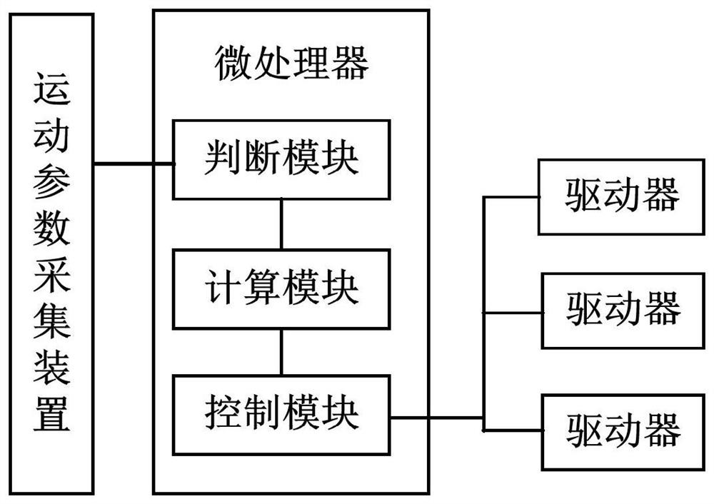
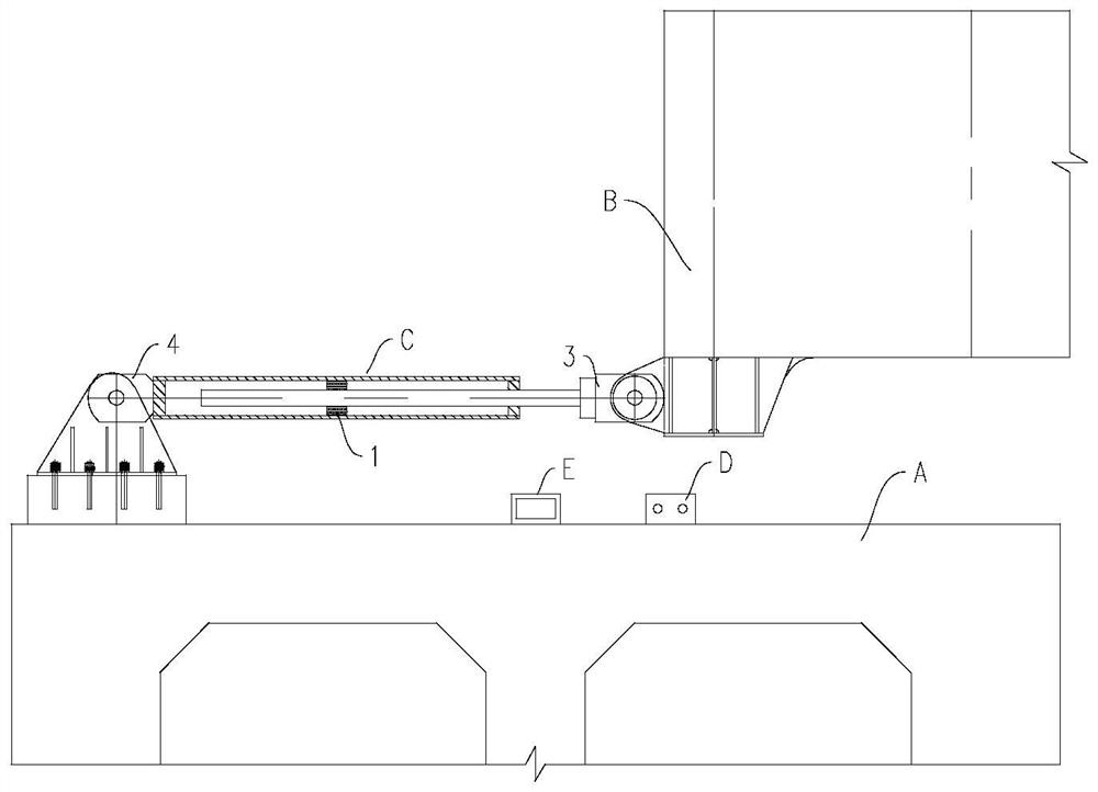
[0050] see figure 1 As shown, an embodiment of the present invention provides a control system for a bridge installed with a viscous damper, the control system comprising:

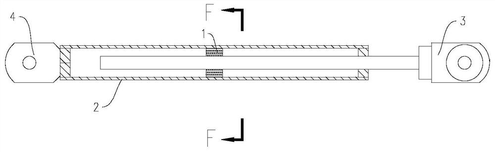
[0051] A viscous damper C, which connects the pier A and the beam end B of the bridge; the viscous damper C includes a cylinder 2 and a reciprocating piston 1 in the cylinder 2, on the piston 1 There are a plurality of passages 11 communicating with both sides of the piston 1, and switch assemblies with the same number as the passages 11. The switch assemblies include a switch element 12 for conducting or blocking the passage 11 and a a driver 13 connected to the switch element 12;

[0052] A motion parameter collection device D, which is arranged on the bridge pier A, and is used to collect the current motion parameters of the beam end B;

[0053] The microprocessor E is connected with the motion parameter acquisition device D and all the drivers 13; the microprocessor E is used to calculate the channel...


PUM


Abstract

The invention discloses a control system and a control method for a bridge equipped with a viscous damper. The control method includes the following steps: Step 1: Install the viscous damper between the pier and the beam end of the bridge in advance; the viscous damper The device includes a cylinder and a piston that can reciprocate in the cylinder. The piston is provided with a plurality of passages connecting both sides of the piston, and a switch assembly with the same number of passages. The switch assembly includes a switch for conducting or blocking the passage. part and a driver connected with the switch part; step 2: collect the current motion parameters of the beam end; step 3: calculate the number of channels to be cut off according to the preset reference motion parameters and the collected current motion parameters, and generate The driving signal is used to control the driver to drive the switching element to turn on or cut off the corresponding channel. The purpose of the present invention is to drive each driver to turn on or cut off each channel according to the motion state of the detected beam end, dynamically adjust the damping force, and reduce the longitudinal cumulative displacement of the beam end.

Description

technical field [0001] The invention relates to the technical field of bridge design, in particular to a control system of a bridge equipped with a viscous damper and a control method thereof. Background technique [0002] Long-span suspension bridges produce significant longitudinal displacements at the beam ends of the stiffening beams under the action of vertical live loads, which is a feature of the structure itself. Taking the driving of the car on the main beam as an example, unlike the wind load or the earthquake load, the driving of the car is a daily behavior, so the longitudinal displacement of the beam end is continuous, that is, if there are vehicles on the suspension bridge, the main beam of the suspension bridge will be uninterrupted. The longitudinal reciprocating movement of the ground also leads to a large cumulative displacement of the beam end of the main beam. [0003] The harm caused by the frequent reciprocating longitudinal movement of the main girder...

Claims


Application Information

Patent Timeline
Patent Type & Authority Patents(China)
IPC IPC(8): E01D19/00E01D11/02
CPCE01D11/02E01D19/00
Inventor 高宗余肖海珠董学智王东晖傅战工唐贺强罗扣王东绪于俊杰彭凌风谢馨蔡銮郑建超
Owner CHINA MAJOR BRIDGE ENERGINEERING
Why Eureka
Try Eureka