Rural toilet cleaning device and toilet flushing method thereof

A clean and flushing technology, applied in water supply devices, flushing toilets, flushing equipment with water tanks, etc., can solve problems such as instability, unclean flushing, insufficient water pressure, etc., and achieve fast and convenient water pressure and convenient flushing , the effect of increasing water pressure

Pending Publication Date: 2020-03-31
邱小彪
View PDF0 Cites 0 Cited by
  • Summary
  • Abstract
  • Description
  • Claims
  • Application Information

AI Technical Summary

Problems solved by technology

[0003] In order to solve the problem of unclean toilet flushing due to insufficient and unstable water pressure in ru

Method used


Image

  • Rural toilet cleaning device and toilet flushing method thereof

Examples


Embodiment 1

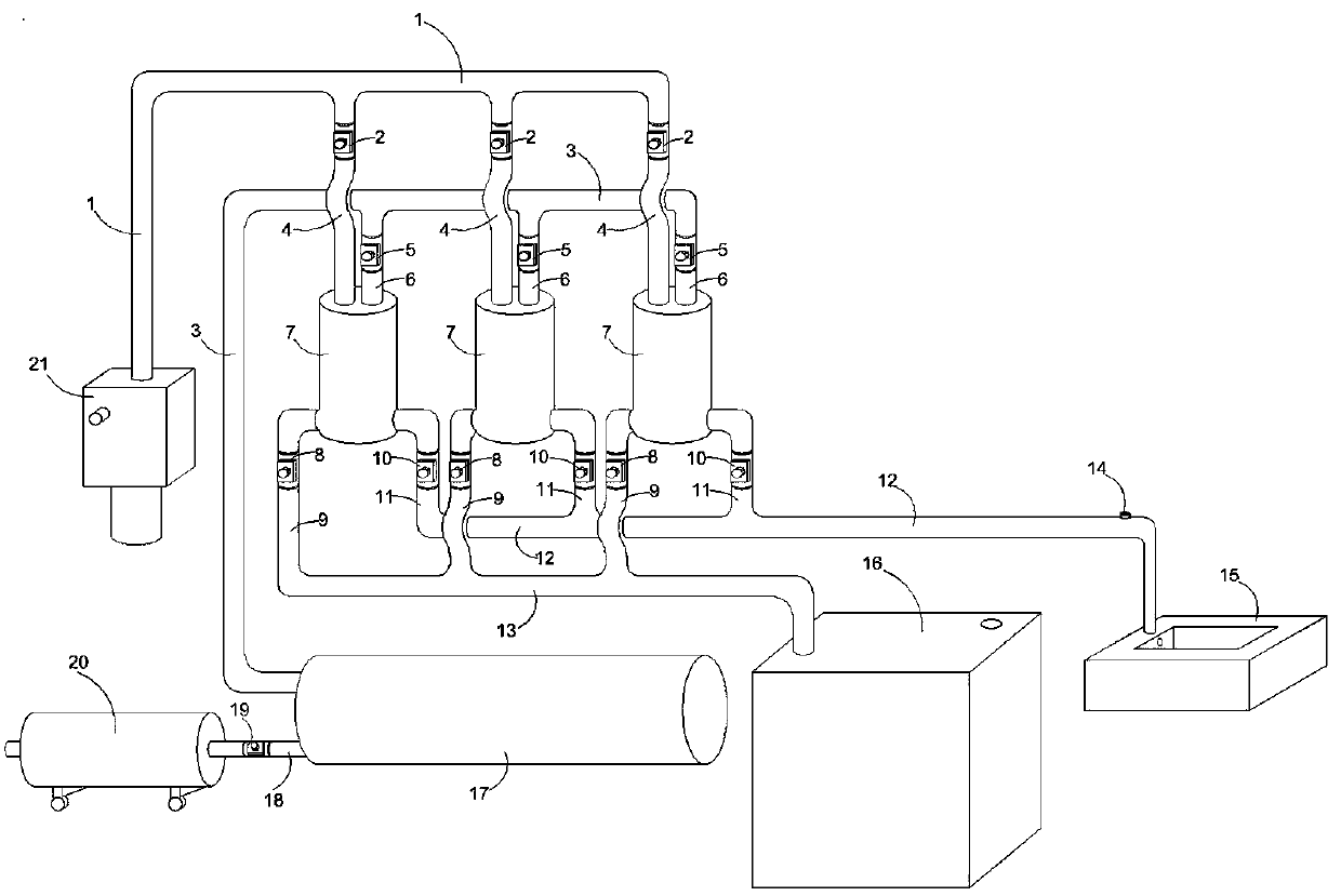
[0029] A farm toilet cleaning device, its structure is as follows figure 1 As shown, it includes a control system, and also includes a pressurized flushing system matched with the control system; the pressurized flushing system includes a working chamber group composed of a plurality of working chambers 7 arranged in parallel, a water suction main pipe 13, a water outlet main pipe 12, Suction main pipe 1 and inflatable main pipe 3, any working chamber 7 is provided with water suction branch pipe 9 and water outlet branch pipe 11, water suction branch pipe 9 is connected with water suction main pipe 13, water outlet branch pipe 11 is connected with water outlet main pipe 12, water suction main pipe 13 The inlet of the water storage tank 16 is connected, and the outlet of the water outlet main pipe 13 is connected with the sanitary ware 15; any working chamber 7 is provided with an inflatable branch pipe 6 and an air suction branch pipe 4, and the inflatable branch pipe 6 is conn...

Embodiment 2

[0038] A cleaning device for farm toilets, which is different from Embodiment 1 in that: the gas control valve 19 is a one-way valve.

[0039] The method for flushing the toilet with the above-mentioned farm toilet cleaning device has the following steps:

[0040] The first step, water absorption: after the farm toilet cleaning device is successfully installed, the water suction port of the water suction main pipe 13 is connected with the water storage tank 16, and the water outlet of the water outlet main pipe 12 is connected with the sanitary ware outlet. Before the device starts to work, the power supply must be turned on, and the work button of the PLC controller should be activated to start preparations. Before being ready to open, the gas storage bin 17 and the three working bins 7 are all in the emptying waiting state, and the inside and outside of the working bins 7 are under the same pressure, and the interior is full of air. After the start-up work starts, the syste...


PUM


Abstract

The invention belongs to the technical field of toilet flushing, and particularly discloses a rural toilet cleaning device. The device comprises a control system and further comprises a pressurizing flushing system matched with the control system. The pressurizing flushing system comprises a working bin set composed of a plurality of working bins arranged in parallel, a water suction main pipe, awater outlet main pipe, an air suction main pipe and an air inflation main pipe. Any working bin is provided with a water suction branch pipe and a water outlet branch pipe; the water suction branch pipe is communicated with the water suction main pipe, the water outlet branch pipe is communicated with the water outlet main pipe, an inlet of the water suction main pipe is communicated with the water storage tank, and an outlet of the water outlet main pipe is communicated with the sanitary appliance; any working bin is provided with an inflation branch pipe and an air suction branch pipe, theinflation branch pipe is communicated with the inflation main pipe, and the air suction branch pipe is communicated with the air suction main pipe; an inlet of the inflation main pipe is communicatedwith an air storage bin; the air storage bin is connected with an air compressor; a vacuum pump is arranged at the outlet of the suction main pipe; and the control system comprises a PLC controller. The invention further discloses a toilet flushing method using the device.

Description

technical field [0001] The invention belongs to the technical field of toilet flushing, and in particular relates to an agricultural toilet cleaning device and a toilet flushing method thereof. Background technique [0002] With the improvement of the living standards of rural residents, the sanitation and comfort of traditional farm toilets can no longer meet the growing needs of farmers for a better life. At present, the mainstream household toilet sanitary ware on the market mainly relies on the flow and pressure of water to flush the sanitary ware. The problem of intermittent supply of source pressure water directly restricts the popularization of household toilets in rural areas. The specific reasons are as follows: Over the years of reform and opening up, the penetration rate of tap water in rural areas has increased significantly. , but the water supply in many rural areas is not uniformly supplied by the municipal pipe network, and most of them are collectively centr...

Claims


Application Information

Patent Timeline
IPC IPC(8): E03D11/02E03D3/10E03D5/01
CPCE03D3/10E03D5/01E03D11/02
Inventor 邱小彪
Owner 邱小彪
Why Eureka
Try Eureka