
Anti-backflow centrifugal fan system

A centrifugal fan and anti-backflow technology, applied in radial flow pumps, cooling/ventilation/heating transformation, components of pumping devices for elastic fluids, etc., can solve the problem of temperature rise of electronic components and acceleration of electronic components Aging, affecting user experience and other issues, to achieve the effect of accelerating aging, reducing backflow, and improving user experience

Inactive Publication Date: 2020-03-31
SHENZHEN WEIBU INFORMATION
View PDF6 Cites 0 Cited by
  • Summary
  • Abstract
  • Description
  • Claims
  • Application Information

AI Technical Summary

Problems solved by technology

However, the defect of the existing fan is that the distance between the air inlet and the air outlet is relatively close, and it is easy to cause the hot air blown out to be sucked back into the system again, resulting in an increase in the temperature of the shell of the system and the temperature of the electronic components, and the acceleration of the electronic components. Device aging and affecting user experience
[0003] Moreover, a gap of 0.8 mm to 1.0 mm needs to be reserved between the fan and the heat dissipation module. The gap at this position will generate partial air flow backflow. Therefore, the air flow rate of the traditional centrifugal fan system is equal to the air intake surface of the fan from the case. flow minus return flow
[0004] Therefore, the existing centrifugal fan system still needs to be improved and developed

Method used


Image

  • Anti-backflow centrifugal fan system
  • Anti-backflow centrifugal fan system
  • Anti-backflow centrifugal fan system

Examples


Embodiment Construction

[0023] In order to make the above objects, features and advantages of the present invention more comprehensible, specific implementations of the present invention will be described in detail below in conjunction with the accompanying drawings.

[0024] The terms used herein in the description of the present invention are for the purpose of describing specific embodiments only, and are not intended to limit the present invention. As used herein, the term "and / or" includes any and all combinations of one or more of the associated listed items.

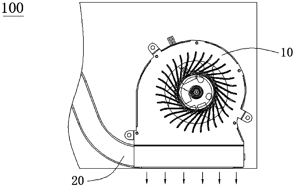
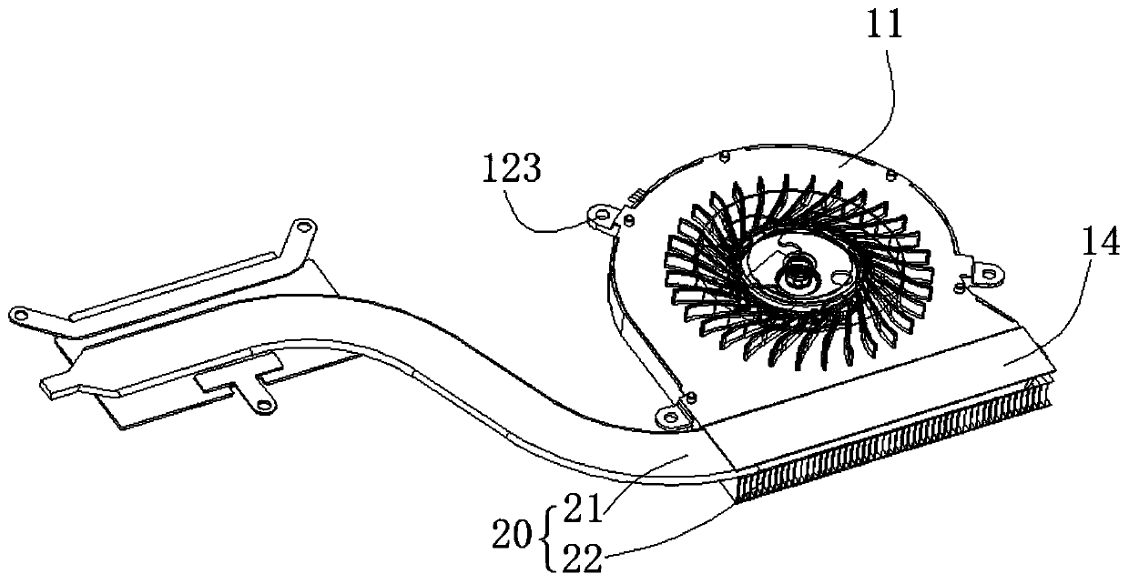
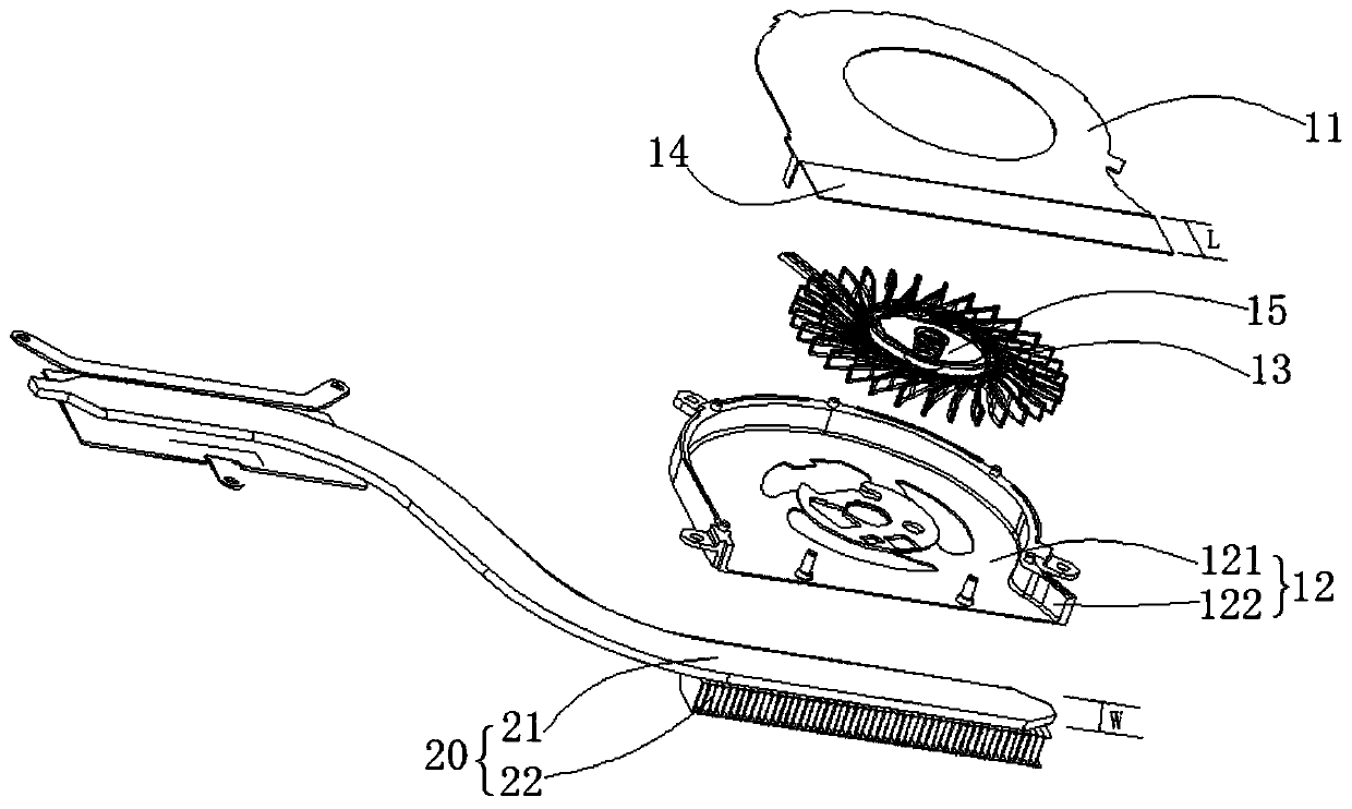
[0025] Please also refer to figure 1 , figure 2 and image 3 , is an anti-backflow centrifugal fan system 100 provided by an embodiment of the present invention.

[0026] The anti-backflow centrifugal fan system 100 includes an anti-backflow centrifugal fan 10 and a cooling module 20; the anti-backflow centrifugal fan 10 includes: an anti-backflow fan upper cover 11, a centrifugal fan lower cover 12, a centrifugal fan blade 13 and T...


PUM


Abstract

The invention discloses an anti-backflow centrifugal fan system. The anti-backflow centrifugal fan system comprises an anti-backflow centrifugal fan and a heat dissipation module; the anti-backflow centrifugal fan comprises an anti-backflow fan upper cover, a centrifugal fan lower cover, centrifugal fan blades and a motor assembled with the centrifugal fan blades; the centrifugal fan lower cover comprises a centrifugal fan bottom shell, and a side wall formed by upwards extending along the edge of the centrifugal fan bottom shell; accommodating space is formed between the anti-backflow fan upper cover and the centrifugal fan lower cover, and is used for accommodating the centrifugal fan blades and the motor; the heat dissipation module comprises a heat pipe and fins arranged on the heat pipe; the anti-backflow fan upper cover outwards extends to form an extension part; the extension part extends to the top of the heat pipe; the extension length L of the extension part is not smaller than the width W of the heat pipe; and hot air currents are taken outside the system, so that the exhaust flow of the system is equal to the flow of the fan from a shell intake surface without generating backflow in the system.

Description

technical field [0001] The invention belongs to the technical field of heat dissipation of electronic products, and in particular relates to an anti-backflow centrifugal fan system. Background technique [0002] A traditional centrifugal fan system generally includes a fan and a cooling module. However, the defect of the existing fan is that the distance between the air inlet and the air outlet is relatively close, and it is easy to cause the hot air blown out to be sucked back into the system again, resulting in an increase in the temperature of the shell of the system and the temperature of the electronic components, and the acceleration of the electronic components. Device aging and affecting user experience. [0003] Moreover, a gap of 0.8 mm to 1.0 mm needs to be reserved between the fan and the heat dissipation module. The gap at this position will generate partial air flow backflow. Therefore, the air flow rate of the traditional centrifugal fan system is equal to th...

Claims


Application Information

Patent Timeline
Patent Type & Authority Applications(China)
IPC IPC(8): F04D29/42F04D29/58F04D17/16F04D25/08H05K7/20
CPCF04D17/16F04D25/08F04D29/4226F04D29/582F04D29/5853H05K7/20
Inventor 丁永波黄建新苏绍光
Owner SHENZHEN WEIBU INFORMATION
Learn More