Air source oil purification device
A purification device and source oil technology, applied in refrigeration and liquefaction, chemical instruments and methods, filtration circuits, etc., can solve problems such as the inability to achieve dehydration function, and achieve the effect of wide temperature range, wide application and precise temperature control
- Summary
- Abstract
- Description
- Claims
- Application Information
AI Technical Summary
Problems solved by technology
Method used
Image
Examples
Embodiment 1
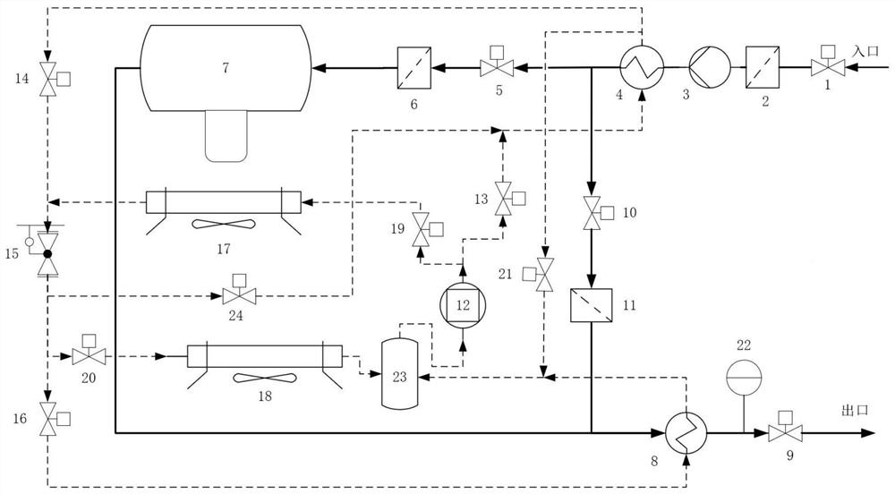
[0026] combine figure 1 , air source oil purification device, including inlet door 1, inlet protection filter 2, oil suction pump 3, inlet heat exchanger 4, dehydration system isolation door 5, dehydration system protection filter 6, dehydration module 7, outlet heat exchanger 8 , exit door 9, impurity filtration system isolation door 10, fine filter 11, compressor 12, isolation door 13 before oil inlet heating, isolation door 14 after oil inlet heating, throttling device 15, outlet heat exchanger isolation door 16, Air-cooled condenser 17, air-cooled evaporator 18, condenser front isolation door 19, evaporator front isolation door 20, inlet heat exchanger to liquid storage tank isolation door 21, outlet moisture sensor 22, liquid storage tank 23, Isolation door 24 before oil inlet cooling; said air source oil purification device includes oil circulation system and heating and cooling circulation system;
[0027] The oil circulation system includes: inlet door 1, inlet protec...
Embodiment 2
[0035] In actual production, the working process of the air source oil purification device during heating operation is as follows:
[0036] a) Heating oil temperature to filter impurities
[0037] The oil system valves (1, 10, 9 are open), the other valves are closed, and the oil suction pump is turned on, the oil to be heated in the system passes through the inlet valve (1) → inlet protection filter (2) → oil suction pump (3) → Inlet heat exchanger (4) shell side → impurity filtration system isolation door (10) → fine filter (11) → outlet heat exchanger (8) → outlet door (9) forms an oil circuit circulation. In addition, the compressor (12) runs, and the refrigerant is compressed by the compressor to form a heating cycle. Compressor (12)→isolating door before oil heating (13)→inlet heat exchanger (4) tube side→isolating door after oil heating (14)→throttle device (15)
[0038] → front isolation door of the evaporator (20) → air-cooled evaporator (18) → liquid storage tank (...
Embodiment 3
[0046] In actual production, the working process of the air source oil purification device during cooling operation is as follows:
[0047] Impurities need to be filtered but the system oil temperature is too high and beyond the tolerance range of the filter element
[0048] The oil system valves (1, 10, 9 are open), the other valves are closed, and the oil suction pump is turned on, the oil to be heated in the system passes through the inlet valve (1) → inlet protection filter (2) → oil suction pump (3) → Inlet heat exchanger (4) shell side → impurity filtration system isolation door (10) → fine filter (11) → outlet heat exchanger (8) → outlet door (9) forms an oil circuit circulation. In addition, the compressor (12) runs, and the refrigerant is compressed by the compressor to form a heating cycle. Compressor (12)→isolation door in front of condenser (19)→air-cooled condenser (17)→throttling device (15)→isolation door in front of oil inlet cooling (24)→inlet heat exchanger ...
PUM
 Abstract
Description
Claims
Application Information
 - R&D
- Intellectual Property
- Life Sciences
- Materials
- Tech Scout
- Unparalleled Data Quality
- Higher Quality Content
- 60% Fewer Hallucinations
Browse by: Latest US Patents, China's latest patents, Technical Efficacy Thesaurus, Application Domain, Technology Topic, Popular Technical Reports.
© 2025 PatSnap. All rights reserved.Legal|Privacy policy|Modern Slavery Act Transparency Statement|Sitemap|About US| Contact US: help@patsnap.com

