
Wastewater treatment system

A wastewater treatment system and water seal technology, applied in the field of wastewater treatment, can solve the problems of low space utilization, difficult installation, waste of exhaust gas, etc., and achieve the effects of reduced operating costs, high space utilization, and small footprint

Pending Publication Date: 2022-04-08
CITIC ENVIROTECH GUANGZHOU CO LTD
View PDF6 Cites 0 Cited by
  • Summary
  • Abstract
  • Description
  • Claims
  • Application Information

AI Technical Summary

Problems solved by technology

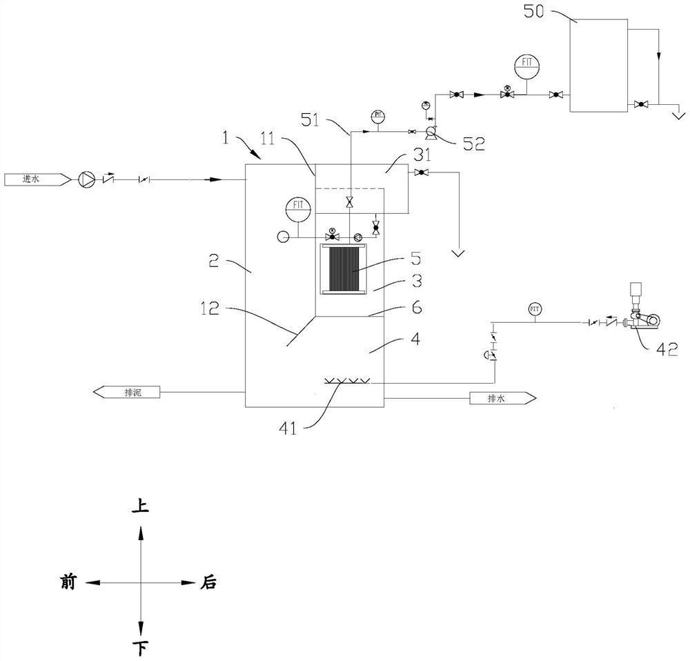
However, there are still many problems in the actual application process. For example, 1) MBR membrane frame is fixed by guide rails, which has high requirements for design and civil construction. There are problems such as difficult installation, difficult fixing, membrane frame floating, and uneven membrane aeration. Daily operation and maintenance cause great difficulties; 2) The membrane aerator is installed at the bottom of the membrane frame, which is easy to cause sludge at the bottom of the membrane pool; 3) Anoxic pool, aerobic pool, and membrane pool are independent of each other and are generally arranged horizontally. The space utilization rate is low; and the horizontally arranged aerobic tank and the membrane tank have different design depths required for the tank body, which has an adverse effect on the design and construction of the civil structure; 4) A / OMBR aerobic tank aeration system , Membrane tank aeration system, and sludge return system are independent, with many equipments and complex systems; 5) The aerobic tank and the membrane tank use their own aeration systems, and a large amount of tail gas in the aerobic tank needs to be deodorized and discharged, causing a large number of Exhaust gas is wasted, and the dissolved oxygen (DO) in the traditional A / O MBR aerobic tank and membrane tank is controlled above 2mg / L and 5mg / L respectively. On the one hand, there are defects such as low aeration utilization rate and high energy consumption; On the other hand, the return of the high dissolved oxygen sludge mixture in the membrane tank or the aerobic tank to the anoxic tank will destroy the anoxic environment of the anoxic tank and cause adverse effects on denitrification and denitrification. Therefore, the traditional A / O MBR There is a practical limit to the denitrification

Method used


Image

  • Wastewater treatment system
  • Wastewater treatment system
  • Wastewater treatment system

Examples


Embodiment 1

[0076] Embodiment 1: see Figure 13 , when the membrane flux is 18LMH, the air volume fluctuates from 5 to 12Nm3 / h, and the sludge concentration is maintained between 11000 and 12000mg / L. The change of water permeability is shown in the figure below. 0.18LMH / bar.h.

Embodiment 2

[0077] Example 2: see Figure 14 In this example, when the membrane operating flux is 30LMH, the sludge concentration is 4000-14000mg / L, and the air volume is 4-8Nm3 / h, the membrane system operates stably, and the decay rate of water permeability is about 0.16LMH / bar.h.

[0078] During the operation of Examples 1 and 2, the floating and mud collection conditions of the floating membrane frame 50 are always good, and the water permeability of the membrane operation is always stable, which proves that the floating membrane frame 50 and the combined aeration system are technically feasible.

[0079] The comparison between the embodiment of the present invention and traditional A / O MBR:


PUM


Abstract

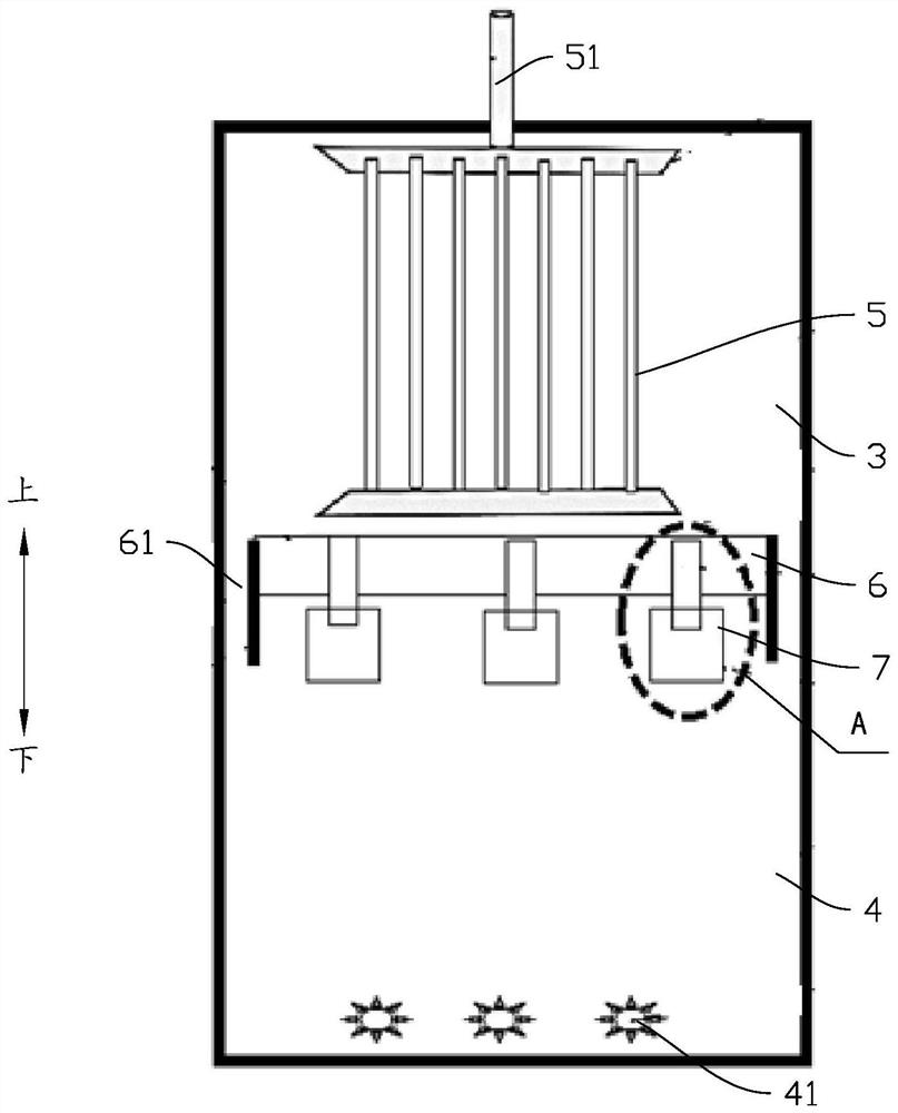
The invention discloses a wastewater treatment system which comprises a reactor, a partition plate is arranged in the reactor, an anoxic tank is formed in front of the partition plate in the inner space of the reactor, a membrane tank is formed in rear of the partition plate in the inner space of the reactor, and an aerobic tank is formed below the membrane tank at the bottom of the reactor. The anoxic tank is communicated with the lower part of the aerobic tank, a first aeration device is arranged in the aerobic tank, a reflux channel is arranged at the periphery of the top of the membrane tank, sludge mixed liquid in the membrane tank can turn over to the reflux channel under the action of gas stripping, the reflux channel is provided with an anoxic reflux pipeline connected to the anoxic tank and an aerobic reflux pipeline connected to the aerobic tank, and a membrane module is arranged in the membrane tank. The membrane module is connected with a water producing pipe. The anoxic tank, the aerobic tank and the membrane tank form a horizontal and vertical combination in spatial arrangement to form an integrated three-region structure, so that the space utilization rate is high, the occupied area is small, and sludge can form a large circulation flow state among the anoxic tank, the aerobic tank and the membrane tank.

Description

technical field [0001] The invention is used in the field of waste water treatment, and in particular relates to a waste water treatment system. Background technique [0002] The A / O MBR process has been successfully applied to industrial wastewater treatment in industries such as cosmetics, medicine, metal manufacturing, textiles, slaughterhouses, dairy products, food, beverages, paper and pulp, oil refining industry and chemical plants, landfill leachate, etc. . However, there are still many problems in the actual application process. For example, 1) MBR membrane frame is fixed by guide rails, which has high requirements for design and civil construction. There are problems such as difficult installation, difficult fixing, membrane frame floating, and uneven membrane aeration. Daily operation and maintenance cause great difficulties; 2) The membrane aerator is installed at the bottom of the membrane frame, which is easy to cause sludge at the bottom of the membrane pool; ...

Claims


Application Information

Patent Timeline
Patent Type & Authority Applications(China)
IPC IPC(8): C02F3/30
Inventor 刘建林谢杰彭赞国陈嘉豪刘红广李永红
Owner CITIC ENVIROTECH GUANGZHOU CO LTD
Learn More