Full-automatic submarine pipeline inspection robot for ocean engineering

A technology for inspection robots and submarine pipelines, applied in the direction of pipe components, special pipes, mechanical equipment, etc., can solve the problems of easy overturning, long distance, unstable walking, etc., to improve the traveling speed, increase the contact area, and reduce friction. The effect of resistance

Active Publication Date: 2020-03-31
广州道彰工程科技有限公司
View PDF7 Cites 9 Cited by
  • Summary
  • Abstract
  • Description
  • Claims
  • Application Information

AI Technical Summary

Problems solved by technology

[0004] 1. The existing submarine pipeline inspection robots mostly use multi-legged crawling or wheeled type. No matter which method is used, due to the long distance of the ocean pipeline and the complicated working environment of the ocean pipeline, when using the foot crawling type, obstacles will be encountered. It is difficult for the inspection robot to overcome obstacles. When four-wheel drive is used, the walking is unstable and prone to overturning;
[0005] 2. The existing submarine pipeline inspection robots mostly use camera devices to take pictures of the areas that the robots pass by, but since the camera devices are used to take pictures during the inspection robot’s travel, it is easy to cause unclear pictures of the internal conditions of the pipeline. At the same time, the position of most camera devices on the inspection robot is fixed, and it is easy to have a dead angle in the shooting of the pipeline, which leads to the incomplete inspection of the internal situation of the submarine pipeline by the staff, which has great limitations.

Method used


Image

  • Full-automatic submarine pipeline inspection robot for ocean engineering
  • Full-automatic submarine pipeline inspection robot for ocean engineering
  • Full-automatic submarine pipeline inspection robot for ocean engineering

Examples


Embodiment Construction

[0036] The following will clearly and completely describe the technical solutions in the embodiments of the present invention with reference to the accompanying drawings in the embodiments of the present invention. Obviously, the described embodiments are only some, not all, embodiments of the present invention. Based on the embodiments of the present invention, all other embodiments obtained by persons of ordinary skill in the art without making creative efforts belong to the protection scope of the present invention.

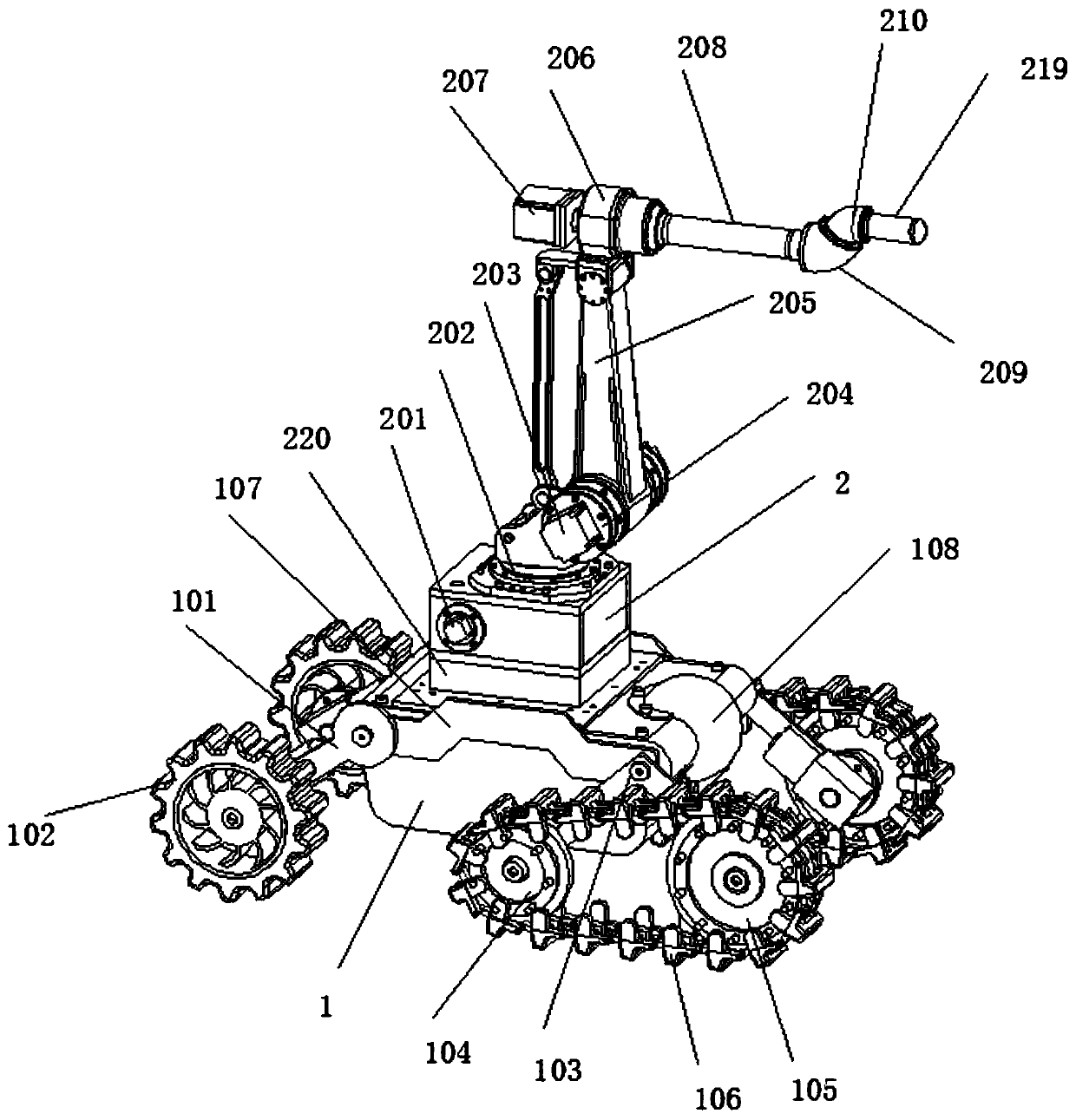
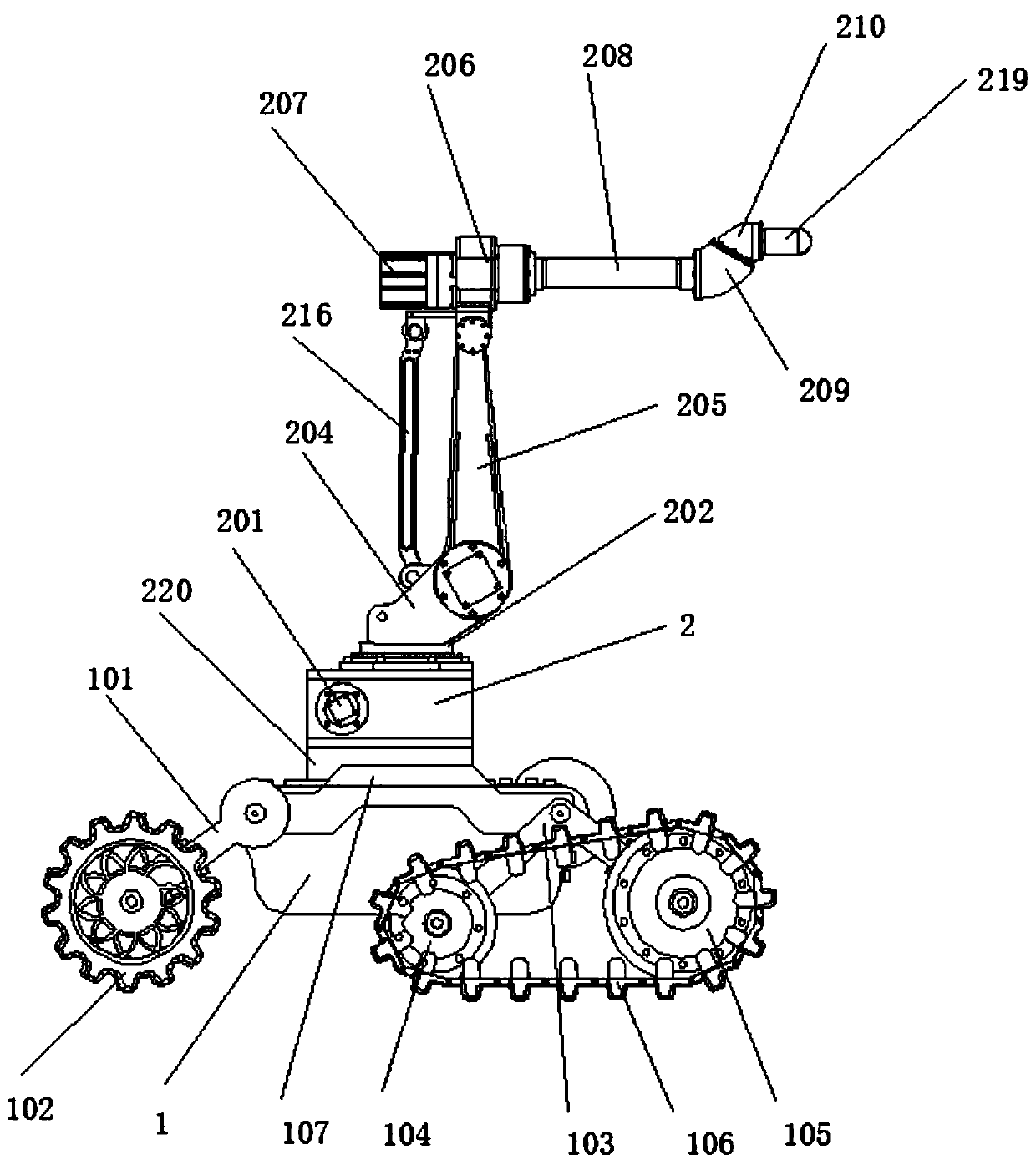
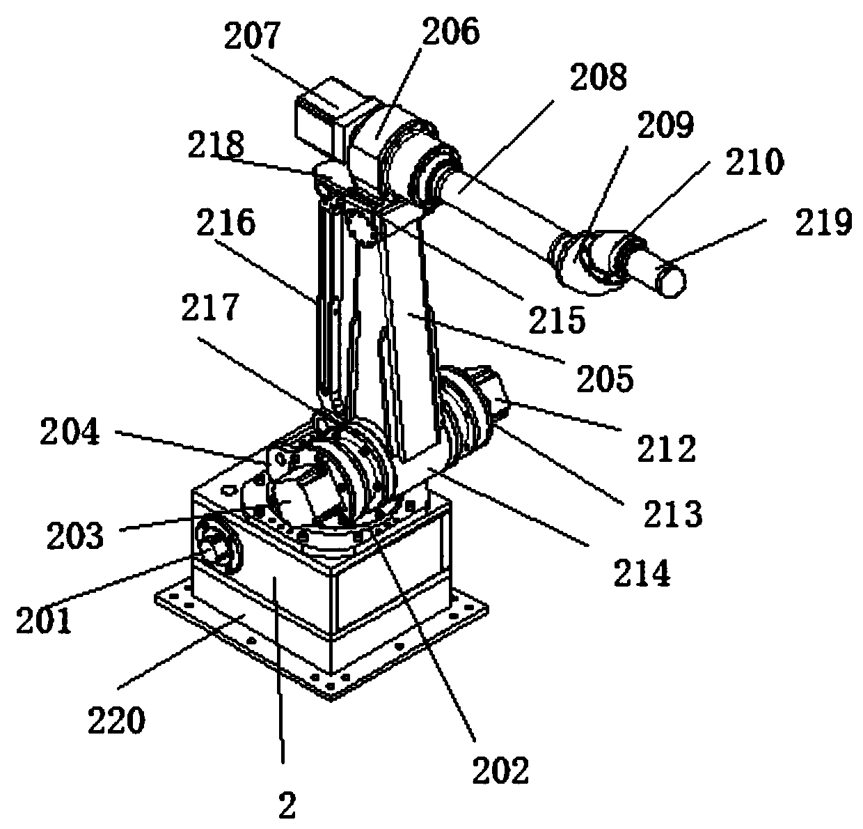
[0037] see Figure 1-8 , in an embodiment of the present invention, a fully automatic subsea pipeline inspection robot for marine engineering includes a traveling vehicle body 1 and a photographing frame 2, a camera 108 is arranged on the traveling vehicle body 1, and a camera 108 is mounted on the photographing body frame 2. A camera body 219 is provided, and the camera body frame 2 is fixedly arranged on the surface of the traveling vehicle body 1 through th...


PUM


Abstract

The invention discloses a full-automatic submarine pipeline inspection robot for ocean engineering. The full-automatic submarine pipeline inspection robot comprises a walking vehicle body and a shooting body frame, wherein a camera is arranged on the walking vehicle body, a camera body is arranged on the shooting body frame, and the shooting body frame is fixedly arranged on the surface of the walking vehicle body through a base. According to the full-automatic submarine pipeline inspection robot, a wheel type and crawler type combined mode is adopted as advancing power of the walking vehiclebody, walking wheels and crawlers are independently driven by stepping motors, so that the walking vehicle body has enough power for walking in a submarine pipeline; and a 360-degree panoramic camerais arranged on the walking vehicle body, when the walking vehicle body walks in the submarine pipeline, the situation in the pipeline is shot through the 360-degree panoramic camera, when the problemsof corrosion, deformation, cracks and the like are generated in the submarine pipeline, the situation in the submarine pipeline is shot through the camera body, so that the dynamic and static combination of the 360-degree panoramic camera and the camera body in the shooting process is realized, and the practicability of the inspection robot is higher.

Description

technical field [0001] The invention belongs to the technical field of pipeline inspection machinery and equipment, in particular to a fully automatic submarine pipeline inspection robot for ocean engineering. Background technique [0002] In recent years, with the development of offshore oil and gas resources, especially the exploitation of deep water and marginal oil fields, the construction scale of marine engineering has also become larger and larger, and submarine pipelines are an important part of current marine engineering. The laying methods of submarine pipelines mainly include No matter which laying method is adopted, the pipe dragging method and the pipe laying ship method are very difficult to lay submarine pipelines. At the same time, the working environment of submarine pipelines is very harsh. During long-term use, due to chemical corrosion, mechanical damage, crustal movement, etc. Corrosion, deformation, cracks, fatigue damage or potential internal defects o...

Claims


Application Information

Patent Timeline
IPC IPC(8): F16L55/32F16L55/40F16L101/30
CPCF16L55/32F16L55/40F16L2101/30
Inventor 陈亚平钟爱丽
Owner 广州道彰工程科技有限公司
Why Eureka
Try Eureka