
A Requirement Modeling and Verification Method for Hardware Logic Design

A technology of hardware logic and verification method, applied in the direction of CAD circuit design, etc., can solve problems such as inability to verify, achieve the effect of inspection accuracy, clear logic, and shorten the circuit design cycle

Active Publication Date: 2021-07-20
DALIAN UNIV OF TECH
View PDF0 Cites 0 Cited by
  • Summary
  • Abstract
  • Description
  • Claims
  • Application Information

AI Technical Summary

Problems solved by technology

[0004] This application aims at the defect that verification cannot be performed in the requirements analysis stage in the current integrated circuit design process, and provides a hardware logic design-oriented requirements modeling and verification method. This method can automatically complete the logic by simply filling the form. Verification, to achieve the effect of pre-verification

Method used


Image

  • A Requirement Modeling and Verification Method for Hardware Logic Design
  • A Requirement Modeling and Verification Method for Hardware Logic Design
  • A Requirement Modeling and Verification Method for Hardware Logic Design

Examples


Embodiment Construction

[0034] The specific embodiments of the present invention will be described in detail below with reference to the accompanying drawings. The described embodiments are only some of the embodiments of the present invention, but not all of the embodiments.

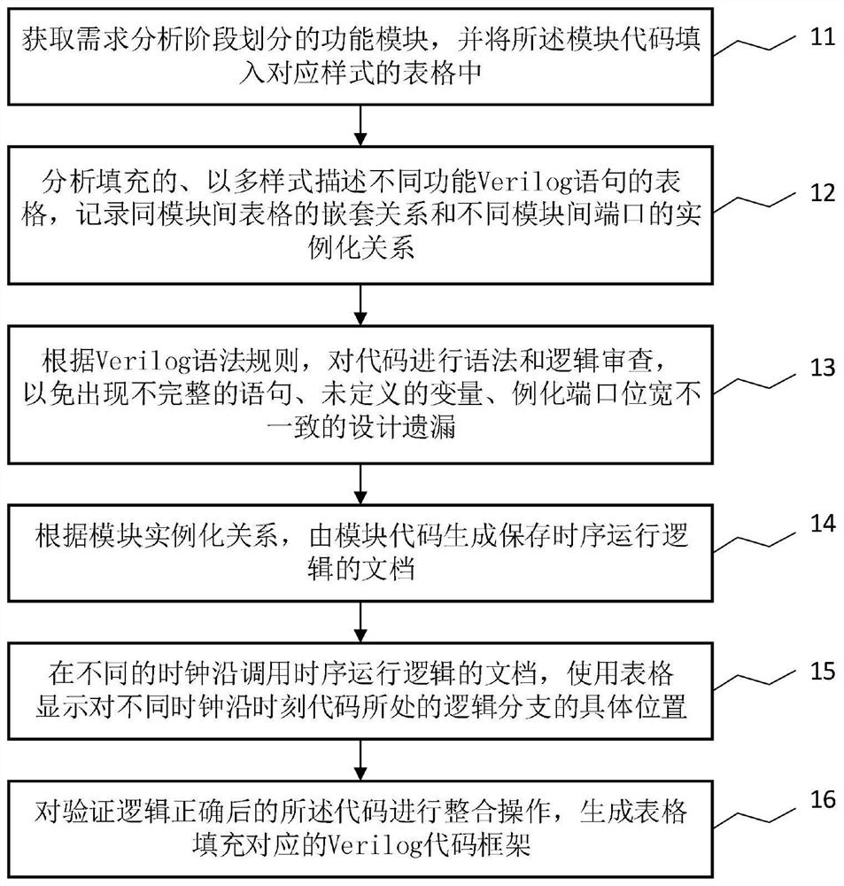
[0035] A requirement modeling and verification method for hardware logic design, such as figure 1 The detailed implementation steps are as follows:

[0036] 11. Obtain the functional modules divided in the requirement analysis stage, and fill in the module codes into the corresponding style table. This embodiment is a design of a serial communication controller, and the functional module is composed of three modules: a top module, a receiving module and a sending module.

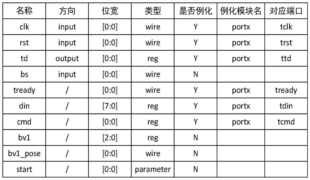
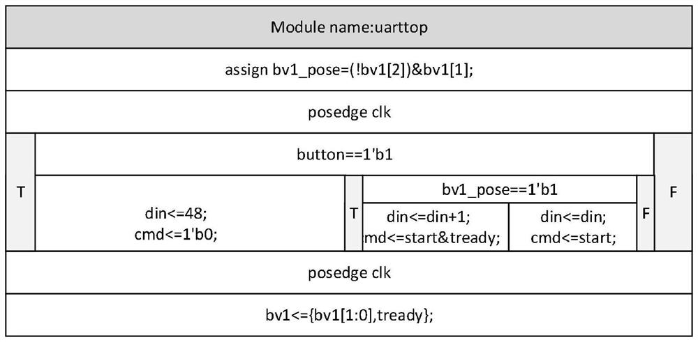
[0037] 12. Analyze the filled tables that describe different functional Verilog HDL statements in multiple styles, and record the nesting relationship between tables in the same module and the instantiation relationship between ports between different modu...


PUM


Abstract

The invention discloses a requirement modeling and verification method oriented to hardware logic design, which includes step 1: obtaining the functional modules divided by the requirement analysis stage, and filling the functional module codes into a table of the corresponding style; step 2: analyzing Filled tables that describe Verilog HDL statements of different functions in multiple styles, record the nesting relationship of tables between the same modules and the instantiation relationship of ports between different modules; Step 3: Review the syntax and logic of the code; Step 4: By the module Code generation saves the document of timing operation logic; Step 5: Call the document of timing operation logic at different clock edges, and use the table to display the specific position of the logic branch of the code at different clock edge times; Step 6: After verifying that the logic is correct The codes are integrated to generate the corresponding Verilog HDL code framework for table filling. This method can automatically verify the logic in a simple way of filling the form, and achieve the effect of prior verification.

Description

technical field [0001] The invention belongs to the technical field of integrated circuit verification, in particular to a requirement modeling and verification method oriented to hardware logic design. Background technique [0002] For increasingly complex integrated circuits, any small design error can lead to circuit paralysis. Defects in the design process of integrated circuits can be found through verification work, reducing the possibility of design errors. At present, the verification of integrated circuits is mainly divided into formal verification and simulation verification. Formal verification uses mathematical theorems to verify the functional consistency of code in the integrated circuit design phase, and uses an exhaustive approach to perform a complete search of all possible results. The simulation verification needs to input the excitation signal into the system to be tested, and verify the correctness of the circuit function through the simulation feedbac...

Claims


Application Information

Patent Timeline
Patent Type & Authority Patents(China)
IPC IPC(8): G06F30/33
Inventor 王洁曹雪邓双敏周宽久侯刚
Owner DALIAN UNIV OF TECH
Learn More