
Broadband low-profile dual circularly polarized planar antenna

A technology of dual circular polarization and flat-panel antenna, which is applied in the direction of antenna, antenna array, antenna grounding switch structure connection, etc., and can solve the problems of narrow impedance bandwidth, high profile, narrow bandwidth, etc.

Inactive Publication Date: 2020-03-31
UNIV OF ELECTRONICS SCI & TECH OF CHINA
View PDF8 Cites 3 Cited by
  • Summary
  • Abstract
  • Description
  • Claims
  • Application Information

AI Technical Summary

Problems solved by technology

There are mainly three types of traditional millimeter-wave dual circularly polarized panel antennas. While they have their own advantages, they also have obvious shortcomings of narrow bandwidth or high profile:
The disadvantage is that the 3dB axial ratio bandwidth is difficult to exceed 20%, because the phase difference is formed before the power division network, and the phase difference of the orthogonal guided wave input by its dual-linearly polarized antenna unit is affected by the power division network
Its advantage profile is extremely low; the axial ratio bandwidth is wider, usually more than 20%; its disadvantage is that the impedance bandwidth is narrow, and the reflection coefficient bandwidth below -10dB is difficult to reach 15%.
Because the coupling amount of a single slot is closely related to the frequency and in the rectangular aperture, the aperture utilization rate is low

Method used


Image

  • Broadband low-profile dual circularly polarized planar antenna
  • Broadband low-profile dual circularly polarized planar antenna
  • Broadband low-profile dual circularly polarized planar antenna

Examples


Embodiment Construction

[0039] The following describes the implementation of the present invention through specific specific examples. Those skilled in the art can easily understand other advantages and effects of the present invention from the content disclosed in this specification. The present invention can also be implemented or applied through other different specific embodiments, and various details in this specification can also be modified or changed based on different viewpoints and applications without departing from the spirit of the present invention.

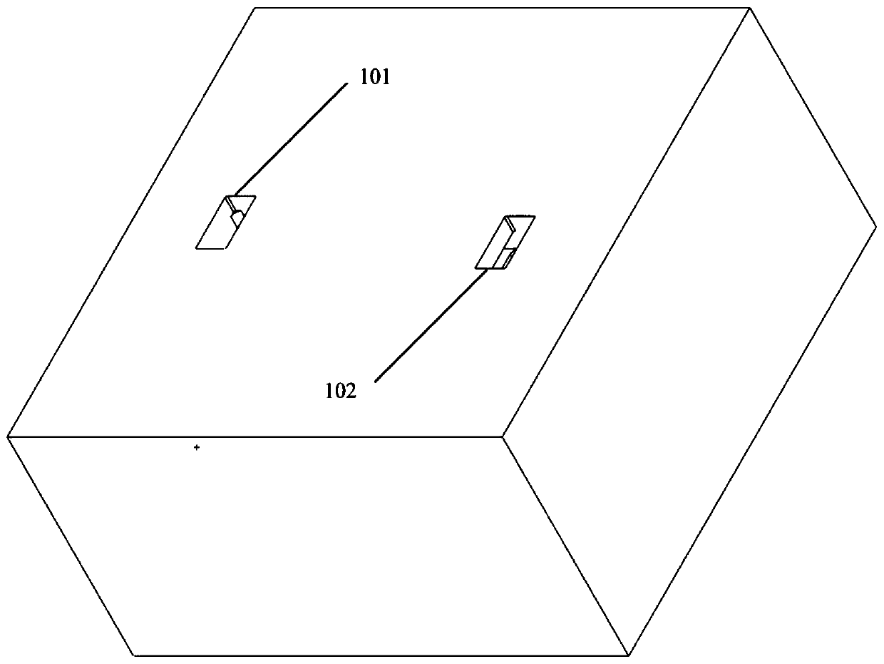
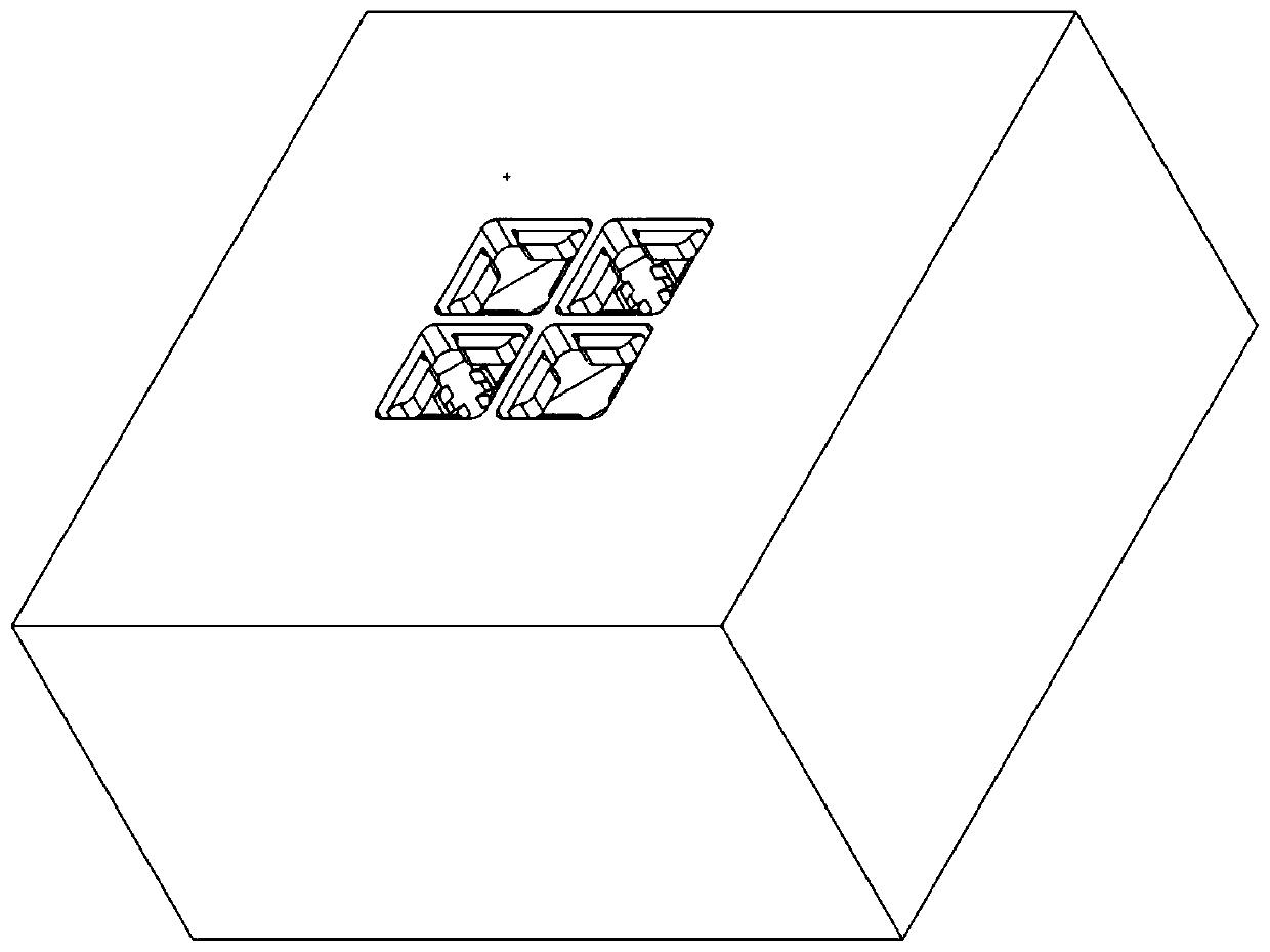
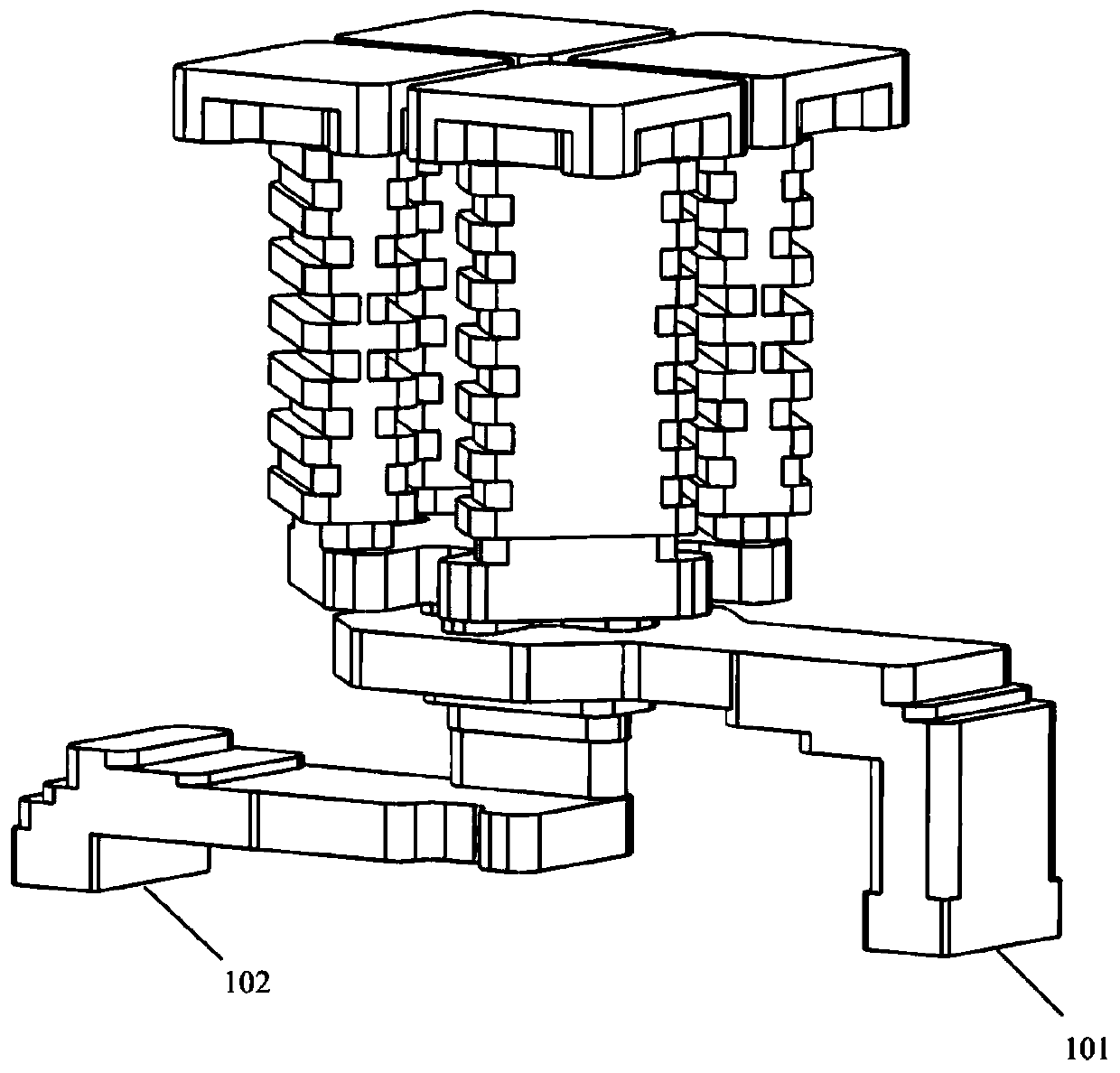
[0040] A broadband low-profile dual circularly polarized flat panel antenna, from bottom to top includes a horizontal and vertical waveguide converter 1, a broadband dual-polarized power splitter 2, a broadband complementary phase shifter 3, and a low-profile quad-ridge horn 4;

[0041] The horizontal and vertical waveguide converter 1 is connected to the dual circular polarization feed port and the broadband dual polarization power splitter 2; ...


PUM


Abstract

The invention provides a broadband low-profile dual circularly polarized planar antenna. The broadband low-profile dual circularly polarized planar antenna comprises a horizontal and vertical waveguide converter, a broadband dual polarized power divider, a broadband complementary phase shifter and a low-profile four-ridge horn from bottom to top, the broadband dual-polarization power divider is used for realizing two pairs of equiamplitude orthogonal in-phase guided wave output; the broadband dual-polarization power divider comprises an orthogonal mode coupler cavity, a cross-shaped gap cavityand a four-ridge power divider cavity, wherein the orthogonal mode coupler cavity is provided with corner cut structures, the four-ridge power divider cavity is provided with corner cut structures ontwo sides of a ridge, the broadband complementary phase shifter comprises a pair of + 45-degree phase shifters and a pair of-45-degree phase shifters, and the low-profile four-ridge horn realizes broadband impedance matching between the broadband complementary phase shifter and air by using the four-ridge structure; broadband impedance matching and dual circularly polarized radiation performanceof the double-end input port under the same frequency band are realized while low profile is realized, and the antenna can also be used as a basic composition unit of a large-scale dual circularly polarized array antenna.

Description

Technical field [0001] The invention relates to the technical field of microwave and millimeter wave antennas, in particular to a broadband low-profile dual circularly polarized flat panel antenna. Background technique [0002] Compared with ku-band, Ka-band has a wider absolute bandwidth, which means that Ka-band communication has a higher channel capacity. Compared with linearly polarized antennas and dual-line polarized antennas, dual circularly polarized antennas have the advantages of strong anti-interference ability and easy matching, and can also achieve frequency reuse. Compared to other forms of high-gain antennas such as reflector antennas and lens antennas, flat panel antennas have a lower profile, which means they are more conformal. Traditional millimeter wave dual circular polarization panel antennas mainly have three methods. While they have their own advantages, they also have obvious shortcomings of narrow bandwidth or high profile: [0003] 1. Use dual-line pola...

Claims


Application Information

Patent Timeline
IPC IPC(8): H01Q1/50H01Q13/02H01Q15/24H01Q21/00
CPCH01Q1/50H01Q13/0275H01Q15/24H01Q21/0006
Inventor 杨峰程铭杨鹏欧阳俊
Owner UNIV OF ELECTRONICS SCI & TECH OF CHINA
Learn More