
Soil remediation device

A technology of soil remediation and crushing device, which is applied in the field of soil remediation and can solve the problems of slow response, low remediation efficiency, uneven dosing, etc.

Active Publication Date: 2020-04-03
山东捷利尔生物工程科技有限公司
View PDF4 Cites 8 Cited by
  • Summary
  • Abstract
  • Description
  • Claims
  • Application Information

AI Technical Summary

Problems solved by technology

[0003] Commonly used contaminated soil remediation technology has attracted much attention. In actual restoration projects, the artificial mode is usually used to apply agents, and the applied agents are solid agents. However, the addition of solid agents has the characteristics of uneven dosing, uneven mixing, and slow response. and other unfavorable factors, the repair efficiency is low, and at the same time it will cause soil compaction, and the repair effect is not ideal

Method used


Image

  • Soil remediation device
  • Soil remediation device
  • Soil remediation device

Examples


Embodiment 1

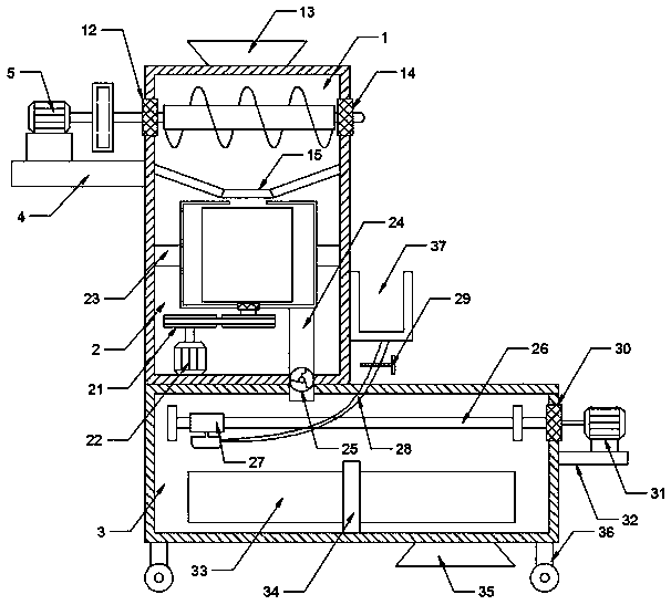
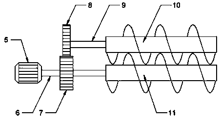
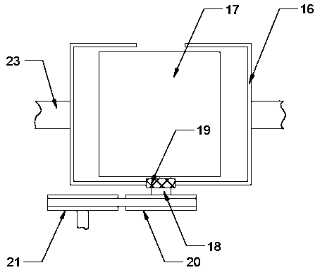
[0022] see Figure 1~3 , in an embodiment of the present invention, a soil remediation device includes a crushing device, a centrifugal device and a stirring device, the crushing device includes a crushing box 1, a second crushing roller 10 and a first crushing roller 11, the crushing box 1 The left outer wall is fixedly connected to the first support plate 4, the top of the first support plate 4 is fixedly connected to the first motor 5, and the output end of the first motor 5 is fixedly connected to the first rotating shaft 6, on which the first rotating shaft 6 The first gear 7 is fixedly socketed, and the first gear 7 and the second gear 8 are connected in transmission. The right end of the second gear 8 is fixedly connected to the second rotating shaft 9, and the right end of the first rotating shaft 6 is fixedly socketed on the first The crushing roller 11, the right end of the second rotating shaft 9 is fixedly sleeved with the second crushing roller 10, the second crus...

Embodiment 2

[0028] see Figure 4 , the present embodiment optimizes the bacteria storage box 37, the top of the right wall of the bacteria storage box 37 is fixedly connected to the strut 42, and the strut 42 is connected to the end cover 41 by hinge rotation, and the right end of the end cover 41 is fixedly connected Magnet 39, the right wall top of described bacteria storage box 37 is fixedly connected with iron block 40, the right side upper end of described pole 42 and the top middle part of described end cover 41 are respectively connected the two ends of spring 38, is provided with end cover 41 To prevent the preparation from being polluted, the provided magnet 39 and iron block 40 facilitate the opening and closing of the end cover 41 .

[0029] The electrical components appearing in this article are all connected with the external main controller and 220V mains electricity, and the main controller can be a conventional known device that plays a control such as a computer.


PUM


Abstract

The invention relates to the field of soil remediation. The invention particularly discloses a soil remediation device. The soil remediation device comprises a crushing device, a centrifugal device and a stirring device, the crushing device comprises a crushing box, a second crushing roller and a first crushing roller; a feeding hole is formed in the top end of the crushing box; an electromagneticvalve is arranged in the center of the bottom surface of the crushing box; the centrifugal device comprises a barrel body and a screen drum; screen holes are formed in the screen drum; the stirring device comprises a threaded rod, a sliding block and blades; a connecting pipe is communicated with the bottom of the barrel body, a fan is arranged in the connecting pipe, a spray head is arranged atthe bottom end of the sliding block and communicated with a rubber hose, the other end of the rubber hose is communicated with a bacterium storage box, a stirring shaft is arranged at the bottom end of the stirring box, and the blades are fixedly connected to the side wall of the stirring shaft. Soil is crushed by using the crushing device, impurities are screened out by using the centrifugal device, soil is remediated with a biological agent, the agent distribution is uniform, and the remediation efficiency is high.

Description

technical field [0001] The invention relates to the field of soil restoration, in particular to a soil restoration device. Background technique [0002] With the continuous expansion of my country's industrial production scale and the rapid development of urbanization, a large amount of heavy metals have entered the soil. Soil polluted by heavy metals will cause changes in the physical, chemical and biological properties of the soil, threatening people's health. The research and development of contaminated soil remediation Practice has become an important content in the field of environmental governance in my country. [0003] Commonly used contaminated soil remediation technology has attracted much attention. In actual restoration projects, artificial mode is usually used to apply agents, and the applied agents are solid agents. However, the addition of solid agents has the disadvantages of uneven dosing, uneven mixing, and slow response. And other unfavorable factors, the ...

Claims


Application Information

Patent Timeline
IPC IPC(8): B09C1/10B02C21/02B02C4/08B02C4/42B02C4/28B02C23/10B04B7/18B04B9/04B01F7/18
CPCB09C1/10B02C21/02B02C4/08B02C4/42B02C4/28B02C23/10B04B7/18B04B9/04B01F27/808B01F27/90
Inventor 范分良宋阿琳付瑞军曹振伟
Owner 山东捷利尔生物工程科技有限公司
Learn More