Cylindrical material forming method

A forming method and the technology of the annular cylinder, which are applied in the field of assembly and manufacturing, can solve the problems of inability to realize automatic transfer and precise positioning, and achieve the effects of improving production efficiency and simplifying the processing process

Active Publication Date: 2020-04-03
长丰吾道智能光电科技有限公司
View PDF8 Cites 8 Cited by
  • Summary
  • Abstract
  • Description
  • Claims
  • Application Information

AI Technical Summary

Problems solved by technology

The defect of this forming method is that after the sheet is bent into an arc shape, it still has great flexibility because the two ends are not connected. During the transfer process, a slight shaking can deform it, so it cann...

Method used


Image

  • Cylindrical material forming method
  • Cylindrical material forming method
  • Cylindrical material forming method

Examples


Embodiment 1

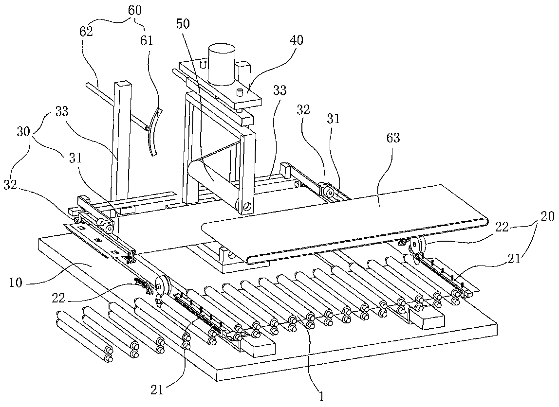
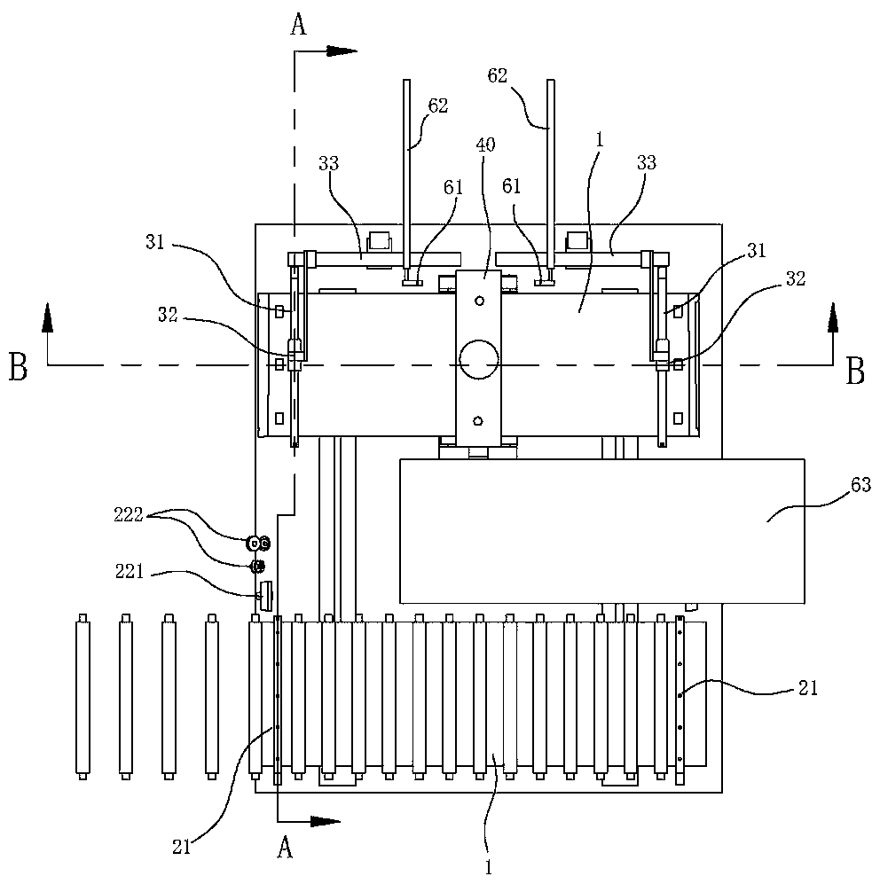
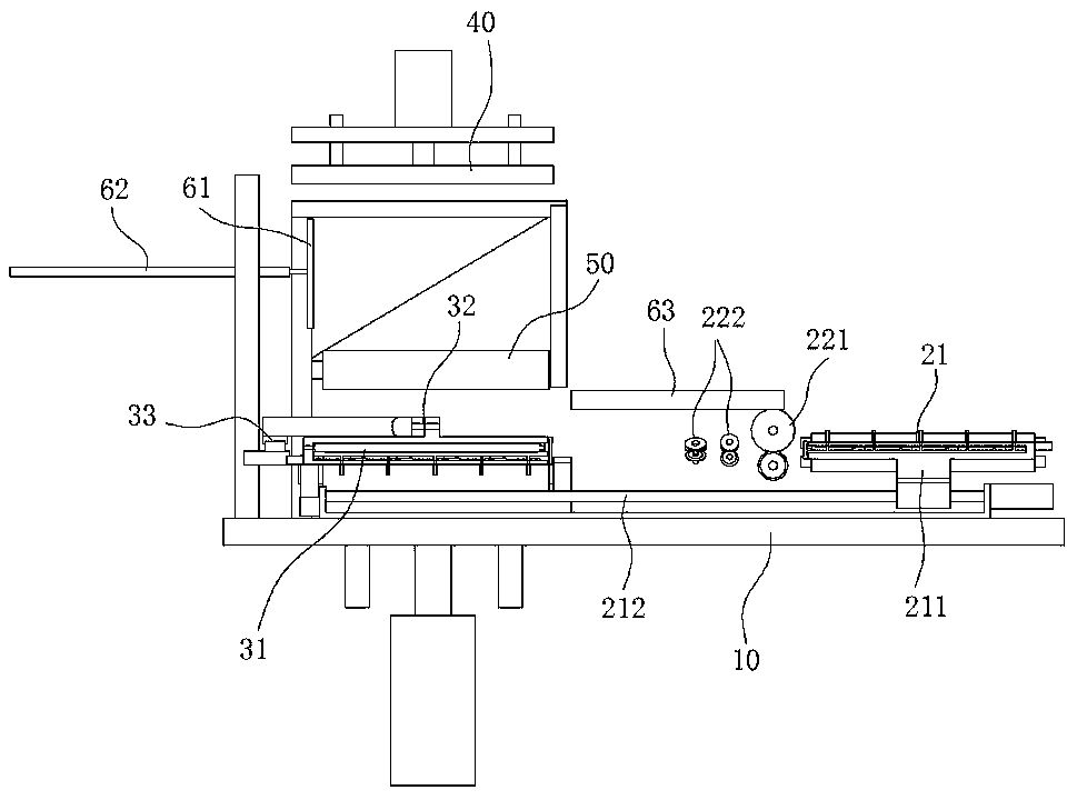
[0035] Such as figure 1 , 2As shown, a washing machine inner cylinder wall forming machine includes a hemming mechanism 20, an overturning mechanism 30, a buckle seam mechanism 40 and a shaping mechanism 50, and the hemming mechanism 20 is used to bend the two ends of the flat sheet 1 into The V-shaped bayonet and the plane sheet 1 are delivered to the overturning mechanism 30, and the overturning mechanism 30 is used to respectively overturn the two ends of the plane sheet 1 by 180° and make the two ends dock at the buckle seam mechanism 40. The buckle seam mechanism 40 is used to crimp and fix the two ends of the planar sheet 1 so that the sheet is connected into an annular tube 2 , and the shaping mechanism 50 is used to roll the annular tube 2 into a cylindrical shape. The invention integrates the rolling and seaming mechanism 40 of the cylindrical part, and adjusts the processing sequence, that is, first seams and then shaping, which solves the defect that the thin-walle...

Embodiment 2

[0047] A tube forming method using the above forming machine, comprising the steps of:

[0048] Step 1: blanking, cutting the metal strip into a rectangular flat sheet 1;

[0049] Step 2: embossing, punching the concave-convex structure and mounting holes on the flat sheet 1 according to the design requirements;

[0050] Step 3: Folding, conveying the flat sheet 1 to the folding mechanism 20, and using the folding mechanism 20 to bend the two ends of the flat sheet 1 into a V-shaped bayonet;

[0051] Step 4: Overturning, conveying the flat sheet 1 after flanging to the overturning mechanism 30, using the overturning mechanism 30 to turn over the two ends of the flat sheet 1 by 180°, and transferring the V-shaped bayonets at the two ends to the buckle seam mechanism 40 buckle at;

[0052] Step 5: buckle the seam, use the buckle seam mechanism 40 to rivet the fastening area of ​​the V-shaped bayonet, so that the two ends of the flat sheet 1 are fixed to form the annular tube 2...


PUM


Abstract

The invention belongs to the technical field of assembly manufacturing, and particularly relates to a cylindrical material forming method. The cylindrical material forming method includes the following steps of blanking, specifically, cutting a metal strip into a rectangular flat sheet; embossing, specifically, stamping the rectangular flat sheet to form a concave-convex structure and an installing hole according to design requirements; edge folding, specifically, using an edge folding mechanism to bend the two ends of the flat sheet to form V-shaped bayonets; turning, specifically, using a turning mechanism to turn the two ends of the flat sheet by 180 degrees, and enabling the V-shaped bayonets at the two ends to be transferred to a seam buckling mechanism for seam buckling; seam buckling, specifically, using the seam buckling mechanism to rivet buckle areas of the V-shaped bayonets; shaping, specifically, driving a shaping roller to rotate to enable the cylindrical material to rotate by at least 360 degrees; and unloading, specifically, transferring the shaped cylindrical material to be moved out from a shaping mechanism, and ending shaping of the cylindrical material. Accordingto the cylindrical material forming method, the machining sequence of the cylindrical material is adjusted, shaping is carried out after seam buckling, the defect of conveying difficulties after rolling of a thin-wall part is solved, automatic forming of the thin-walled cylindrical part is achieved, the processing process is simplified, and the production efficiency is improved.

Description

technical field [0001] The invention belongs to the technical field of assembling and manufacturing, and in particular relates to a tube forming method. Background technique [0002] Thin-walled cylindrical parts such as the inner wall of the washing machine are generally processed in the process of bending first and then buckling, that is, the flat sheet is first rolled out to a certain arc, and then the two ends of the flat sheet are riveted. Press into one. The defect of this forming method is that after the sheet is bent into an arc shape, it still has great flexibility because the two ends are not connected. During the transfer process, a slight shaking can deform it, so it cannot be processed Without precise positioning, it is impossible to realize the automatic transfer of its processing process, which leads to the fact that the processing of such parts still needs to rely on a large number of manual operations at this stage. Contents of the invention [0003] The...

Claims


Application Information

Patent Timeline
IPC IPC(8): B21D35/00B21D39/02B21D43/00B21D5/00B21D5/14B21D3/04B21D45/04B23P23/04
CPCB21D3/04B21D5/002B21D5/14B21D35/00B21D39/02B21D43/003B21D45/04B23P23/04
Inventor 王彬王海峰
Owner 长丰吾道智能光电科技有限公司
Why Eureka
Try Eureka