
Foundation pit support based on real-time feedback

A technology of foundation pit support and real-time feedback, which is applied in foundation structure tests, on-site foundation soil surveys, foundation structure engineering, etc., can solve problems such as potential safety hazards, neglect of importance, and high labor intensity in foundation pits, and achieve The effect of improving the anti-floating performance and bearing capacity, improving the accuracy of vibration monitoring, and improving the accuracy of stress monitoring

Pending Publication Date: 2020-04-03
HUBEI PROVINCIAL WATER RESOURCES & HYDROPOWER PLANNING SURVEY & DESIGN INST
View PDF0 Cites 1 Cited by
  • Summary
  • Abstract
  • Description
  • Claims
  • Application Information

AI Technical Summary

Problems solved by technology

People do not pay enough attention to the stress of the support structure, ignoring its importance, and the accuracy is not high, the flexibility is not strong in real time, it cannot be transmitted over long distances, and the labor intensity is high
Therefore, there is a great potential safety hazard in the foundation pit.
[0004] In the existing technology, the monitoring accuracy of the safety and reliability of the foundation pit support is not high, and the safety performance of the foundation pit support cannot be effectively evaluated, resulting in potential safety hazards in the foundation pit

Method used


Image

  • Foundation pit support based on real-time feedback
  • Foundation pit support based on real-time feedback
  • Foundation pit support based on real-time feedback

Examples


Embodiment Construction

[0026] The present invention will be further described in detail below in conjunction with the accompanying drawings and specific embodiments to facilitate a clear understanding of the present invention, but they do not limit the present invention.

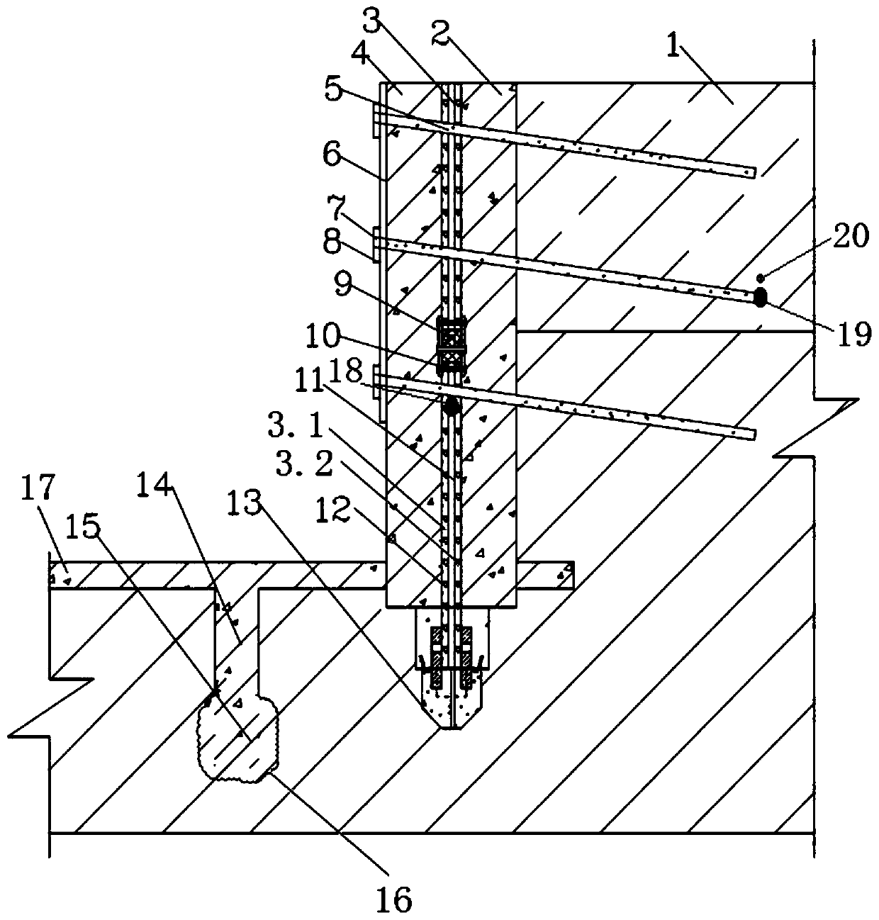
[0027] Such as figure 1As shown, a foundation pit support based on real-time feedback, including main fixed piles 4 and transverse reinforcement rods 5, the main fixed piles 4 are vertically arranged and evenly distributed along the circumference of the side wall of the foundation pit, and the bottom of the main fixed piles 4 is mainly The fixed pile head 13, the bottom of the main fixed pile 4 extends into the soil layer 1 at the bottom of the foundation pit. The side of the main fixed pile 4 away from the foundation pit forms a vertical protective layer 2 . The transverse reinforcing rod 5 passes through the main fixed pile 4 and penetrates into the soil layer 1 of the side wall of the foundation pit downwards. A first vertica...


PUM


Abstract

The invention relates to the technical field of foundation pit supporting, and particularly relates to a foundation pit support based on real-time feedback. The foundation pit support comprises main fixing piles and transverse reinforcing rods, wherein the main fixing piles are vertically arranged and evenly distributed in the circumferential direction of the side wall of a foundation pit; the bottoms of the main fixing piles stretch into a soil layer at the bottom of the foundation pit; the transverse reinforcing rods downwards incline to penetrate through the main fixing piles and stretch into the soil layer on the side wall of the foundation pit; a first vertical blocking and protecting plate and a second vertical blocking and protecting plate which are parallel to each other are vertically arranged in the main fixing piles; the middle of the first vertical blocking and protecting plate and the middle of the second vertical blocking and protecting plate are fixedly connected; a middle reinforcing layer is formed between the first vertical blocking and protecting plate and the second vertical blocking and protecting plate; and a stress sensor used for detecting stress signals ofthe middle reinforcing layer is arranged in the middle reinforcing layer. The first vertical blocking and protecting plate and the second vertical blocking and protecting plate are arranged in the main fixing piles, so that the stable middle reinforcing layer is formed between the two blocking and protecting plates. The stress sensor is arranged in the middle reinforcing layer and used for monitoring the soil stress of the part, and the safety of the foundation pit support can be effectively reflected.

Description

technical field [0001] The invention relates to the technical field of foundation pit support, in particular to a foundation pit support based on real-time feedback. Background technique [0002] When excavating a foundation pit in a high groundwater level area, in order to ensure the normal progress of the construction, it is necessary to dewater the foundation pit. Common foundation pit dewatering methods include dewatering inside the foundation pit, dewatering outside the foundation pit, and synchronous dewatering inside and outside the foundation pit. A lot of engineering experience shows that dewatering the foundation pit can effectively reduce the seepage of groundwater, keep the foundation pit in a dry environment for construction, and prevent quicksand and piping at the bottom of the foundation pit, avoiding the soil at the bottom of the foundation pit And the loss of foundation pit slope soil, effectively improving the stability of the foundation pit. However, when...

Claims


Application Information

Patent Timeline
Patent Type & Authority Applications(China)
IPC IPC(8): E02D17/04E02D1/00E02D33/00E02D19/12E02D5/72
CPCE02D1/00E02D5/72E02D17/04E02D19/12E02D33/00
Inventor 张兵李瑞清刘贤才李文峰别大鹏姚晓敏崔金秀李海涛孙娟娟
Owner HUBEI PROVINCIAL WATER RESOURCES & HYDROPOWER PLANNING SURVEY & DESIGN INST
Learn More