Automatic exhaust device of hydraulic circuit breaker

A hydraulic circuit breaker and automatic exhaust technology, which is applied to valve devices, machines/engines, liquid fuel engines, etc., can solve problems such as unsatisfactory exhaust effects, achieve simple installation, good sealing effect, and avoid cumbersome effects

Active Publication Date: 2020-04-03
STATE GRID ZHEJIANG ELECTRIC POWER CO LTD JIAXING POWER SUPPLY CO
View PDF9 Cites 4 Cited by
  • Summary
  • Abstract
  • Description
  • Claims
  • Application Information

AI Technical Summary

Problems solved by technology

However, the gas in this patent returns to the fuel tank and cannot be discharged out of the de...

Method used


Image

  • Automatic exhaust device of hydraulic circuit breaker
  • Automatic exhaust device of hydraulic circuit breaker
  • Automatic exhaust device of hydraulic circuit breaker

Examples


Embodiment 1

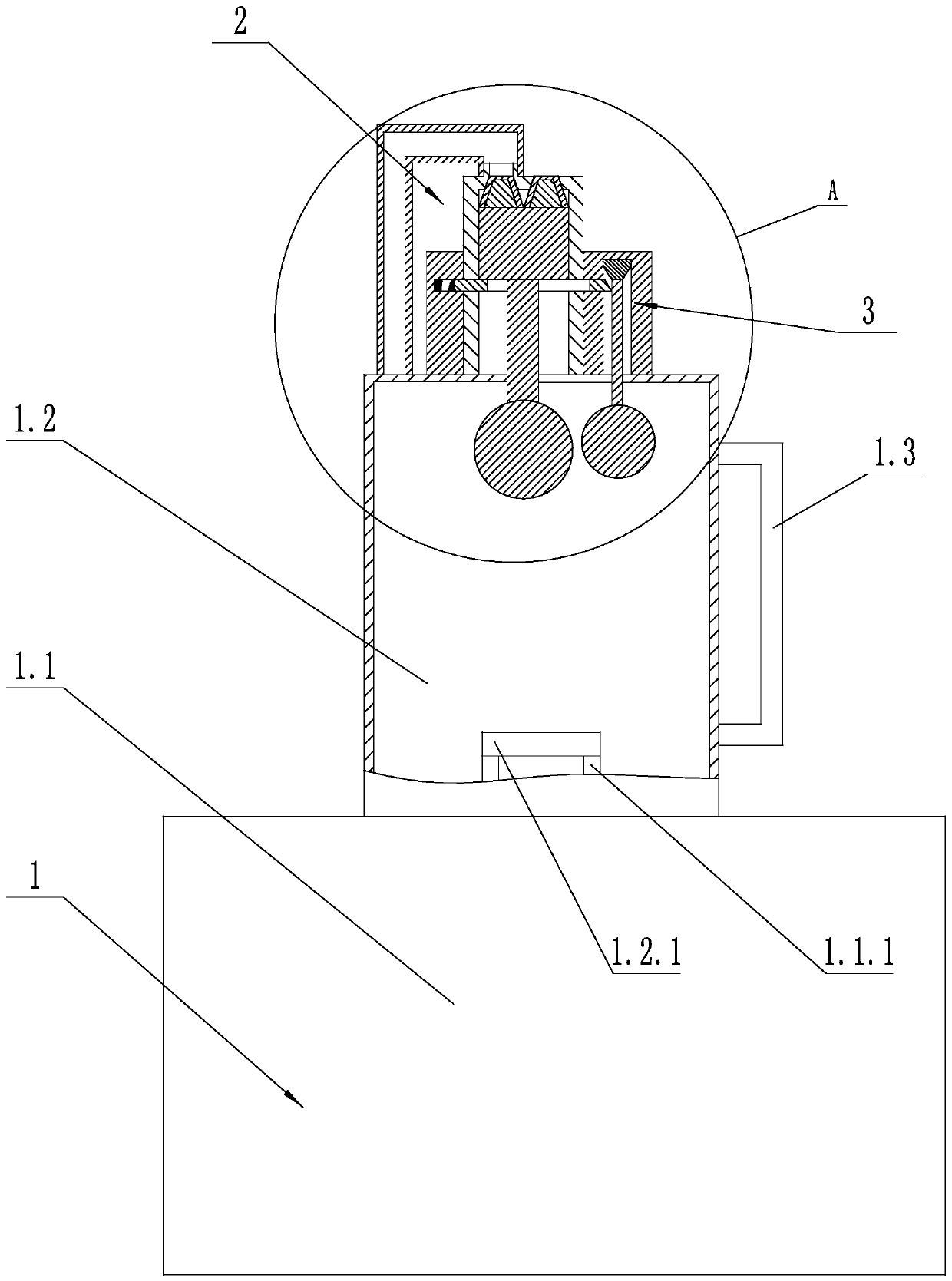
[0030] Such as figure 1 and figure 2 As shown, an automatic exhaust device for a hydraulic circuit breaker includes an oil pump 1. The oil pump 1 includes a pump body 1.1 and an air collecting tank 1.2. The air collecting tank 1.2 is arranged on the top of the pump body 1.1. .1, the bottom of the gas collecting tank 1.2 is provided with an internally threaded hole 1.2.1 adapted to the externally threaded pipe 1.1.1, and the gas collecting tank 1.2 communicates with the pump body 1.1 through the externally threaded pipe 1.1.1, the gas collecting tank 1.2 There is a liquid level display tube 1.3 on the outside; an exhaust assembly 2 is provided above the gas collection tank 1.2, and the exhaust assembly 2 includes an intake pipe 2.1, a connecting pipe 2.2, a slider 2.4 and a first floating ball 2.5;

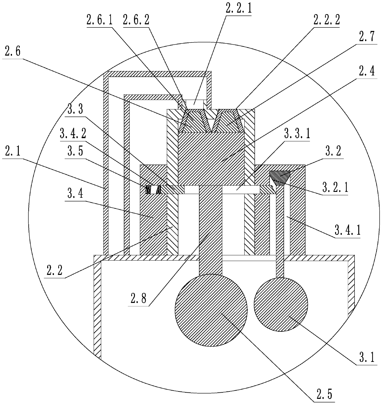
[0031] The upper end of the connecting pipe 2.2 is provided with an air inlet 2.2.1 and an air outlet 2.2.2, the lower end of the connecting pipe 2.2 communicates with the gas co...

Embodiment 2

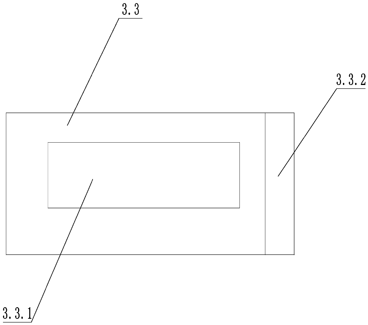
[0035] Such as figure 2 and image 3 As shown, on the basis of Embodiment 1, a hysteresis assembly 3 is also included, and the hysteresis assembly 3 includes a second floating ball 3.1, an unlocking block 3.2, a locking block 3.3, a fixed block 3.4 and a telescopic spring 3.5, and the fixed block 3.4 is provided with The first chute 3.4.1 and the second chute 3.4.2 communicate with each other, the first chute 3.4.1 is vertically arranged, and the unlocking block 3.2 is slidably arranged on the first chute 3.4.1; the second chute 3.4.2 Horizontal setting, the locking block 3.3 is slidably set in the second chute 3.4.2, the telescopic spring 3.5 is set in the second chute 3.4.2, and one end of the telescopic spring 3.5 is connected with the locking block 3.3, stretching The other end of the spring 3.5 is connected with the fixed block 3.4, the second chute 3.4.2 is connected with the connecting pipe 2.2, the locking block 3.3 is provided with an avoidance groove 3.3.1, and the...

Embodiment 3

[0038] Such as Figure 4 As shown, on the basis of Embodiment 2, when the slider 2.4 is lowered to the lowest position, the sliding side is still in contact with the locking block 3.3. The structure can ensure that the locking block 3.3 will not protrude after the slide block 2.4 descends, and ensure that the slide block 2.4 can move up and down freely before returning to the sealing position.


PUM


Abstract

The invention discloses an automatic exhaust device of a hydraulic circuit breaker, which comprises an oil pump, and is characterized in that an exhaust assembly is arranged above the oil pump, the exhaust assembly comprises an air inlet pipe, a communicating pipe, a sliding block and a first floating ball, and the upper end of the communicating pipe is provided with an air inlet and an air outlet; one end of the air inlet pipe is communicated with the oil pump, and the other end of the air inlet pipe is communicated with the air inlet; the sliding block is arranged in the communicating pipe and connected with the communicating pipe in a sliding mode, the first floating ball is arranged in the oil pump and fixed to the sliding block through a connecting rod, the upper end of the sliding block is provided with a first sealing piece and a second sealing piece which are used for sealing the air inlet and the air outlet respectively, the first sealing piece is matched with the air inlet, and the second sealing piece is matched with the air outlet. The automatic exhaust device of the hydraulic circuit breaker provided by the invention can realize the automatic exhaust of an oil pump andavoid the tediousness of manual exhaust. The automatic exhaust device is good in exhaust effect and good in sealing effect.

Description

technical field [0001] The invention relates to the field of high-pressure hydraulic circuit breakers, in particular to an automatic exhaust device for hydraulic circuit breakers. Background technique [0002] As an important component of the power system, the high-voltage circuit breaker is widely used in various substations, power plants and other places, and plays a vital role in industrial production and people's daily life. The high-voltage circuit breaker is a kind of load switch , with short circuit and overload protection. For circuit breakers that have been in operation for many years, it is common for air to enter the hydraulic system. The hydraulic circuit breaker in actual operation drives the oil pump through the motor to drive the low hydraulic oil in the oil tank into the energy storage cylinder, and uses the high hydraulic oil output by the oil pump to compress nitrogen gas for energy storage. In the oil circuit of the oil pump, the oil in the low-pressure ...

Claims


Application Information

Patent Timeline
IPC IPC(8): F16K17/02F16K31/22F04B53/06
CPCF16K17/02F16K31/22F04B53/06
Inventor 李传才蔡宏飞韩中杰俞军闻飞翔牛帅杰周刚
Owner STATE GRID ZHEJIANG ELECTRIC POWER CO LTD JIAXING POWER SUPPLY CO
Why Eureka
Try Eureka