Supercharge Your Innovation With Domain-Expert AI Agents!

Termination assembly

A termination and assembly technology, applied in the direction of pipes/pipe joints/fittings, pipe components, electrical components, etc., to solve problems such as unbalanced load transfer

Active Publication Date: 2020-04-03
JDR CABLE SYST
View PDF7 Cites 0 Cited by
  • Summary
  • Abstract
  • Description
  • Claims
  • Application Information

AI Technical Summary

Problems solved by technology

Any misalignment, however slight, will result in an unbalanced load transfer and therefore a possible weak point or area in the weld between the tube and plate

Method used


Image

  • Termination assembly
  • Termination assembly
  • Termination assembly

Examples


Embodiment Construction

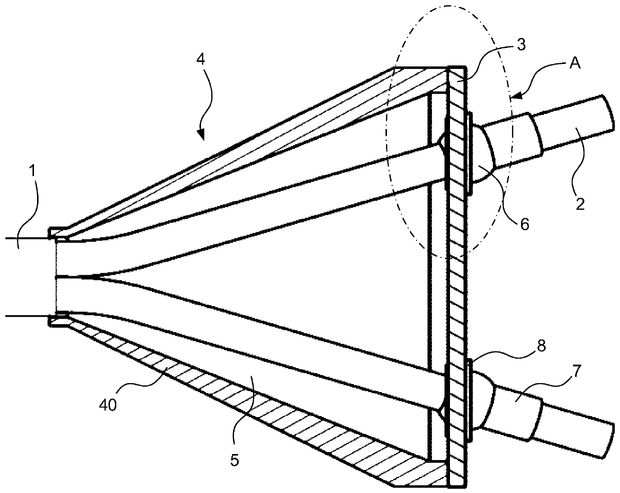
[0031] figure 1An embodiment of a termination assembly 4 for an umbilical 1 according to the invention is shown. In this embodiment, the termination assembly 4 comprises a plurality of umbilical elements, however only two steel pipes 2 are shown in the figure. The pipe 2 extends from the umbilical 1 through the termination cavity 5 of the termination assembly 4 and through corresponding holes in the steel bulkhead plate 3 . Additional umbilical elements will also pass through the bulkhead plate 3 . The bulkhead plate 3 is fixed on the terminal assembly 4 to form a terminal cavity 5 . In the arrangement shown, the conical pot portion 40 forming the body of the termination assembly 4 may be formed in multiple parts connectable together.

[0032] from figure 1 It can be seen that the steel pipe 2 is bent at a slight angle close to the end of the umbilical 1, but is relatively straight. As such, minimal machining of the tube is required to form the termination assembly. This...


PUM


Abstract

The invention relates to an umbilical termination assembly for terminating a cable or umbilical. The termination assembly comprises a plurality of umbilical elements extending from an umbilical and which pass through a bulkhead plate. The seated ball element has a spherical body through which an umbilical element passes. The ball element is seated in a cup member which allows the ball element to rotate through a large range of angles allowing it to be aligned with the umbilical element without the umbilical element needing to be manipulated or forced into position. The umbilical element can then be attached to the ball element which is supported by the cup member on the bulkhead. This allows the axial tension in the umbilical element to be transferred to the bulkhead.

Description

technical field [0001] The present invention relates to a termination assembly. In particular, the invention relates to termination assemblies for cables or umbilicals and methods of assembling such termination assemblies. Background technique [0002] Cables and umbilicals are commonly used to provide equipment with various forms of energy (such as electrical energy, hydraulic energy, pneumatic energy, etc.), signals (electrical signals, optical signals, pressure signals) or consumables, and can be used above and below sea level . Umbilicals may be deployed on the seabed and typically consist of a collection of one or more types of elongated active umbilical elements, including electrical, pneumatic, hydraulic, and chemical. For additional flexibility and mechanical strength, these elements can be wound with additional external parts as required. Umbilicals help provide the necessary control to and from subsea facilities, often by transporting various forms of chemicals,...

Claims


Application Information

Patent Timeline
Patent Type & Authority Applications(China)
IPC IPC(8): F16L5/14F16L5/02F16L55/035H02G3/22
CPCF16C11/0614F16C11/0671F16L5/025F16L5/14F16L25/01F16L39/04H02G3/22F16L5/022F16L55/035F16L11/127F16L11/22B60T11/046F16C11/0638F16C23/045F16D2125/587F16D2125/60
Inventor 菲利普·艾伦·沃德
Owner JDR CABLE SYST
Features
  • R&D
  • Intellectual Property
  • Life Sciences
  • Materials
  • Tech Scout
  • Unparalleled Data Quality
  • Higher Quality Content
  • 60% Fewer Hallucinations
Learn More