
A kind of photoelectric smoke detector ambient light suppression method and system

A smoke detector and ambient light technology, applied in the field of smoke detectors, to achieve the effects of low power consumption, strong suppression capability, and excellent static and dynamic ambient light suppression capability

Active Publication Date: 2022-07-26
BEIJING SENSORO
View PDF6 Cites 0 Cited by
  • Summary
  • Abstract
  • Description
  • Claims
  • Application Information

AI Technical Summary

Problems solved by technology

[0008] Aiming at the shortcomings of the ambient light suppression scheme in the prior art, the present invention provides a photoelectric smoke detector ambient light suppression method and system, which can still provide excellent static light while avoiding the use of complex digital logic or digital operations. and dynamic ambient light suppression capability

Method used


Image

  • A kind of photoelectric smoke detector ambient light suppression method and system
  • A kind of photoelectric smoke detector ambient light suppression method and system
  • A kind of photoelectric smoke detector ambient light suppression method and system

Examples


Embodiment 1

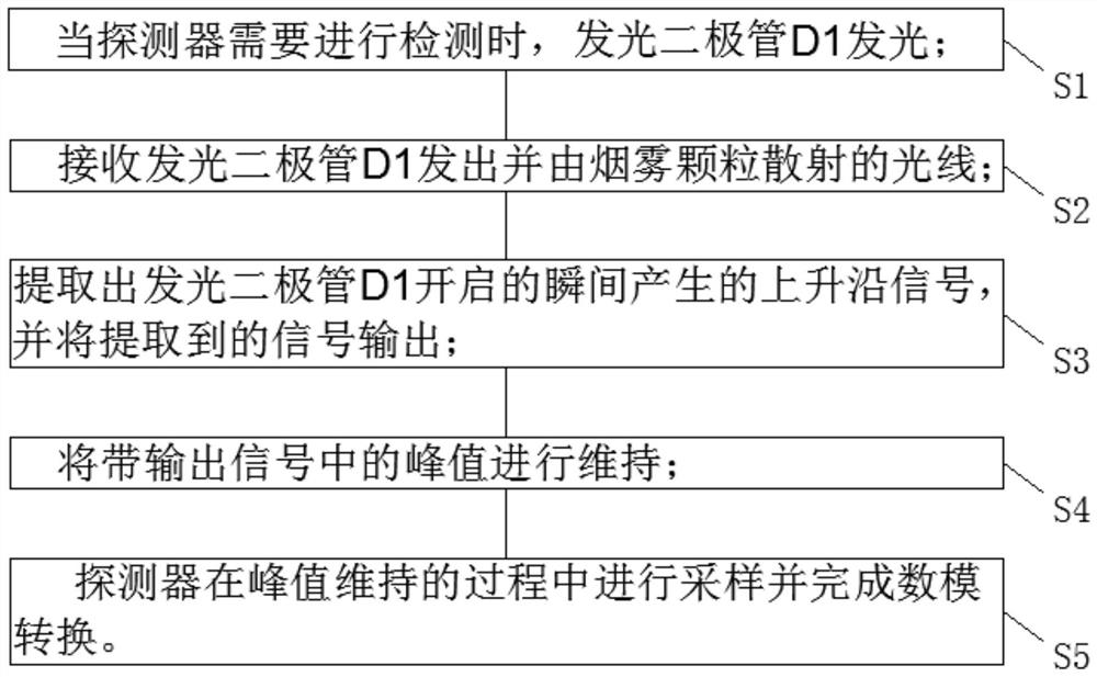
[0050] like figure 1 As shown, this embodiment discloses a method for suppressing ambient light of a photoelectric smoke detector, and the method includes the following steps:

[0051] S1. When the detector needs to detect, the light-emitting diode D1 emits light;

[0052] S2. Receive the light emitted by the light-emitting diode D1 and scattered by the smoke particles;

[0053] S3. Extract the rising edge signal generated at the moment when the light-emitting diode D1 is turned on, and output the extracted signal;

[0054] S4. Maintain the peak value in the band output signal;

[0055] S5. The detector samples and completes digital-to-analog conversion during the peak maintenance process.

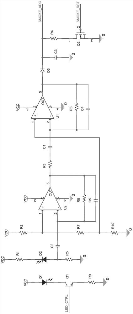
[0056] The light-emitting diode D1 is driven by a light-emitting diode drive circuit to emit light; the light emitted by the light-emitting diode D1 is received by the photo-receiving diode D2; the photo-receiving diode D2 receives the light emitted by the light-emitting diode D1 and sc...

Embodiment 2

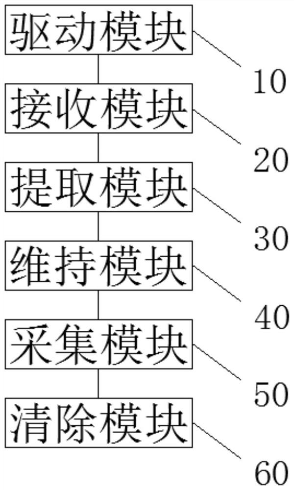
[0064] like figure 2 , image 3 and Figure 4 As shown, this embodiment discloses an ambient light suppression system for a photoelectric smoke detector, and the system includes:

[0065] The driving module 10 is used for driving the light-emitting diode D1 to emit light when the detector needs to perform detection;

[0066] The receiving module 20 is used for receiving the light emitted by the light-emitting diode D1 and scattered by the smoke particles;

[0067] The extraction module 30 is used to extract the rising edge signal generated at the moment when the light-emitting diode D1 is turned on, and output the extracted signal;

[0068] maintaining module 40, for maintaining the peak value in the band output signal;

[0069] The sampling module 50 is used for the detector to sample and complete the digital-to-analog conversion during the peak maintenance process;

[0070] The clearing module 60 is used for clearing the peaks in the circuit before the light-emitting d...


PUM


Abstract

The invention relates to the technical field of smoke detectors, in particular to a method and system for suppressing ambient light of a photoelectric smoke detector. The method includes the following steps: when the detector needs to perform detection, the light-emitting diode D1 emits light; receiving the light emitted by the light-emitting diode D1 and scattered by the smoke particles; extracting the rising edge signal generated when the light-emitting diode D1 is turned on, and extracting the extracted signal Output; maintain the peak value in the output signal; the detector samples and completes the digital-to-analog conversion during the peak maintenance process. The present invention can be used in a point-type light scattering type smoke detector without an optical labyrinth, and can still provide excellent static and dynamic ambient light suppression capabilities under the condition of avoiding the use of complex digital logic or digital operations. It provides a realistic and feasible solution for a low-cost and low-power optical-free labyrinth-point light-scattering smoke detector.

Description

technical field [0001] The invention relates to the technical field of smoke detectors, in particular to a method and system for suppressing ambient light of a photoelectric smoke detector. Background technique [0002] In photoelectric smoke detectors, the influence of ambient light on the receiving tube is usually reduced by the structure of the labyrinth and the design of the optical path. The elimination of ambient light through the design of the maze increases the complexity of the design on the one hand; on the other hand, it also prevents smoke particles from entering the detection area, reducing the detection sensitivity and increasing the response time. [0003] Patent CN104200606 discloses a signal processing method for solving ambient light interference in a point-type light scattering smoke detector without an optical maze. The method uses a transmitting tube to modulate the scattered signal, and then demodulates the smoke concentration signal through spectrum a...

Claims


Application Information

Patent Timeline
Patent Type & Authority Patents(China)
IPC IPC(8): G08B17/103G08B17/107
CPCG08B17/103G08B17/107
Inventor 张宁
Owner BEIJING SENSORO
Learn More