Ultrasound diagnostic equipment

A diagnostic device and ultrasonic technology, applied in the directions of sonic diagnosis, infrasound diagnosis, ultrasonic/sonic/infrasonic diagnosis, etc., can solve problems such as decreased spatial resolution

Active Publication Date: 2022-07-01
HITACHI HEALTHCARE MFG LTD
View PDF19 Cites 0 Cited by
  • Summary
  • Abstract
  • Description
  • Claims
  • Application Information

AI Technical Summary

Problems solved by technology

The filter method can perform imaging by sending and receiving once, but it is necessary to separate the fundamental wave component and the higher harmonic component, so a narrow-band transmission waveform is required, and the spatial resolution is reduced

Method used


Image

  • Ultrasound diagnostic equipment
  • Ultrasound diagnostic equipment
  • Ultrasound diagnostic equipment

Examples


Embodiment 1

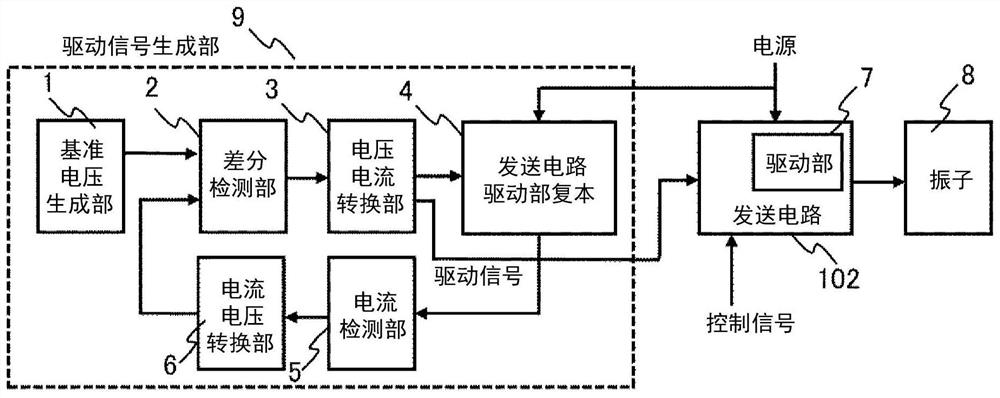
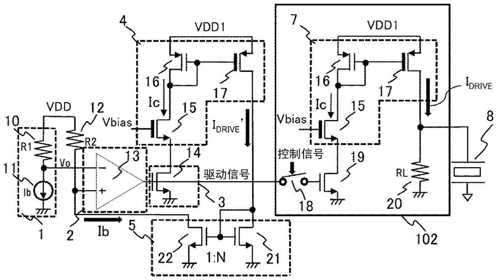
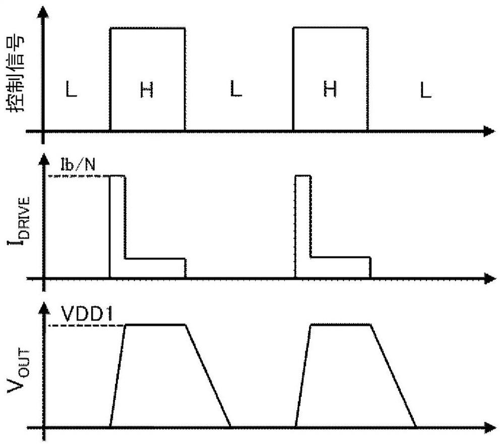
[0033] figure 1 It is a block diagram showing the drive signal generation unit and the transmission circuit according to the first embodiment of the present invention. The drive unit 7 inside the transmission circuit 102 that drives the vibrator 8 outputs a drive current corresponding to the drive signal supplied from the drive signal generation unit 9 to drive the vibrator 8 . At this time, a control signal is input to the transmission circuit 102, and the drive signal is enabled or disabled by the control signal, whereby a drive current flows to the output, and High and Low signals can be generated.

[0034] The drive signal generation unit 9 includes a reference voltage generation unit 1 , a difference detection unit 2 , a voltage-to-current conversion unit 3 , a transmission circuit driving unit replica 4 , a current detection unit 5 , and a current-to-voltage conversion unit 6 . The difference detection unit 2 , the voltage-to-current conversion unit 3 , the transmission...

Embodiment 2

[0053] Figure 5 Example 2 of the present invention is shown. In the second embodiment, the positive and negative driving current can be supplied to the vibrator 8 . The transmission circuit 102 includes a positive-side driver 7a and a negative-side driver 7b, and inputs a positive power supply VDD1, a control signal a, and a driving signal a to the positive-side driver 7a, and inputs a negative power supply VDD2 and a control signal to the negative-side driver 7b b and the drive signal b. The drive signals a and b are generated by the drive signal generating units 9a and 9b, respectively. The outputs of the drive units 7 a and 7 b of the transmission circuit 102 are connected to the vibrator 8 .

[0054] Image 6 Yes Figure 5 internal structure diagram. The driving signal generating unit 9a and the positive side driving unit 7a for generating the positive side driving signal a have been described in the first embodiment. The drive signal generation unit 9b that genera...

Embodiment 3

[0058] Figure 9 Example 3 of the present invention is shown. Embodiment 3 is an application example to the ultrasonic diagnostic apparatus of the present invention. The ultrasonic diagnostic apparatus 300 includes a main frame 201 , an ultrasonic probe 203 connected via a cable 202 , and an image display unit 107 . The ultrasonic transducer 103 is arranged in the ultrasonic probe 203 , and the transmission circuit 102 arranged inside the main frame 201 and the ultrasonic transducer 103 are connected via wiring inside the cable 202 . At this time, the transmission circuit 102 and the drive signal generation unit 9 are arranged inside the main frame 201 . A plurality of ultrasonic transducers 103 and transmission circuits 102 may be arranged.


PUM


Abstract

Provided is an ultrasonic diagnostic apparatus in which the drive current of the vibrator is constant with respect to semiconductor process variations. The ultrasonic diagnostic apparatus includes a vibrator, a drive signal generator that generates a drive signal, and a transmission circuit that outputs a drive current corresponding to the drive signal and drives the vibrator, the transmission circuit passing through a current mirror composed of a low-voltage transistor and a high-voltage transistor A vibrator drive unit that is configured to connect the high-voltage transistor to the vibrator, and a current source that supplies an operating current corresponding to the drive signal to the low-voltage transistor of the vibrator drive unit is configured, and the drive signal generation unit includes A replica of the transmission circuit drive unit having the same structure as the vibrator drive unit, and a feedback control unit that detects the current flowing to the high-voltage transistor of the replica of the transmission circuit drive unit and controls the current to be constant, will The feedback control unit supplies, as the drive signal, a signal applied to a current source that supplies an operating current to a low-voltage transistor of the transmission circuit drive unit to a current source that supplies an operating current to a low-voltage transistor of the vibrator drive unit .

Description

technical field [0001] The present invention relates to an ultrasonic diagnostic apparatus. Background technique [0002] In an ultrasonic diagnostic apparatus, there is an imaging method called tissue harmonic imaging (THI) that visualizes the distortion components generated in the living body. Compared with the normal brightness (Brightness, B) mode imaging, By utilizing the harmonic components, it is possible to reduce the influence of side lobes, artifacts, etc. generated in the fundamental wave, and to achieve higher image quality. In THI, there are two methods: a filter method in which only secondary distortion components generated in a living body are extracted using a filter, and an impulse inversion method in which a fundamental wave component is removed by adding positive and negative symmetrical waves. The filter method can perform imaging by transmitting and receiving once, but it is necessary to separate the fundamental wave component and the harmonic component...

Claims


Application Information

Patent Timeline
Patent Type & Authority Patents(China)
IPC IPC(8): A61B8/00
CPCA61B8/00B06B1/0215B06B2201/76A61B8/4494A61B8/54B06B1/0207B06B1/0622G01S7/52019
Inventor 矢崎彻西元琢真
Owner HITACHI HEALTHCARE MFG LTD
Why Eureka
Try Eureka