
Auxiliary device for CT imaging of heads and necks

A CT imaging and auxiliary device technology, applied in applications, veterinary instruments, instruments used for radiological diagnosis, etc., can solve problems such as large emotional fluctuations, few auxiliary devices, and easy to move

Inactive Publication Date: 2020-04-07
王宁
View PDF0 Cites 3 Cited by
  • Summary
  • Abstract
  • Description
  • Claims
  • Application Information

AI Technical Summary

Problems solved by technology

[0002] With the development and progress of the current society, more and more people like to keep pets. At the same time, people's love for pets is gradually increasing. Now the pet hospital has a relatively complete scale, and the testing equipment of the pet hospital is relatively advanced. Head and neck CT imaging examination is one of the routine examination items for pets, but pets have large emotional fluctuations during the head and neck CT imaging examination process, and are prone to move, which will affect the examination results, especially the head and neck CT of pet dogs. For detection, dogs are aggressive pets, and corresponding measures such as sedatives need to be taken between inspections before detection can be carried out. However, auxiliary devices are still required to fix the limbs, head and neck of pet dogs during the detection process, but existing There are few related auxiliary devices for pet dog head and neck CT detection in the technology

Method used


Image

  • Auxiliary device for CT imaging of heads and necks
  • Auxiliary device for CT imaging of heads and necks
  • Auxiliary device for CT imaging of heads and necks

Examples


Embodiment Construction

[0014] In order to make the purpose, technical solutions and advantages of the embodiments of the present invention clearer, the technical solutions in the embodiments of the present invention will be clearly and completely described below in conjunction with the drawings in the embodiments of the present invention. Obviously, the described embodiments It is a part of embodiments of the present invention, but not all embodiments. Based on the embodiments of the present invention, all other embodiments obtained by persons of ordinary skill in the art without creative efforts fall within the protection scope of the present invention.

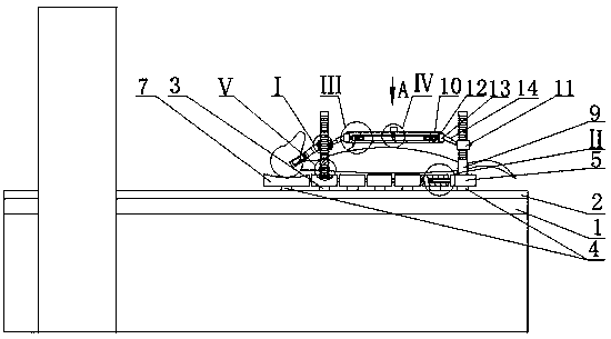
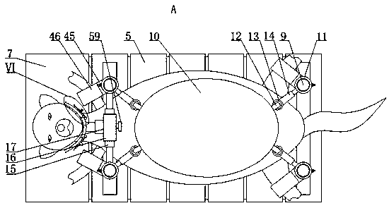
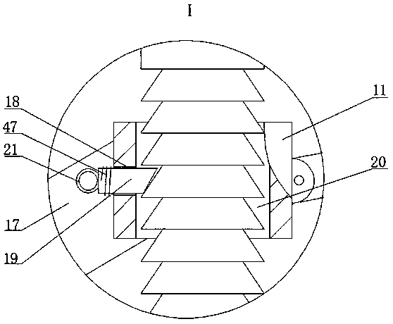
[0015]An auxiliary device for head and neck CT imaging inspection, as shown in the figure, includes a CT machine, a slide rail 2 is fixedly installed on the top surface of the detection table 1 of the CT machine, and the upper part of the slide rail 2 is provided with several horizontally equidistant arrays and The first sliding block 3 that coope...


PUM


Abstract

The invention discloses an auxiliary device for CT imaging of heads and necks. The auxiliary device comprises a CT machine, wherein a sliding rail is fixedly installed on the top surface of a detection table of the CT machine; the upper part of the sliding rail is provided with a plurality of first sliding blocks which are horizontally arranged at an equal interval and are movably matched with thesliding rail; two electric sliding blocks movably matched with the sliding rail are arranged at the outer ends of the sliding rail; the electric sliding blocks are located on the left sides and the right sides of the first sliding blocks respectively; a headrest plate is fixedly installed on the top surface of the electric sliding block located at the left side; movable plates are fixedly installed on the top surfaces of all the first sliding blocks and the top surface of the electric sliding block located at the right side; and horizontal first grooves are formed in the right sides of the movable plates and the headrest plate. The auxiliary device for is used for CT detection of the head and the neck of a pet dog; the four limbs of the pet dog are fixed by limb fixing devices, a head fixing device is adopted for fixing the lower jaw of the head of the pet dog, and the pet dog is comprehensively fixed and is guaranteed to keep a certain posture in the examination process, so examination effect can be effectively guaranteed; and the comfort degree of the pet dog in the examination process is guaranteed due to a design directed at the body shape of the pet dog.

Description

technical field [0001] The invention belongs to the field of medical detection equipment for animals, in particular to an auxiliary device for head and neck CT imaging inspection. Background technique [0002] With the development and progress of the current society, more and more people like to keep pets. At the same time, people's love for pets is gradually increasing. Now the pet hospital has a relatively complete scale, and the testing equipment of the pet hospital is relatively advanced. Head and neck CT imaging examination is one of the routine examination items for pets, but pets have large emotional fluctuations during the head and neck CT imaging examination process, and are prone to move, which will affect the examination results, especially the head and neck CT of pet dogs. For detection, dogs are aggressive pets, and corresponding measures such as sedatives need to be taken between inspections before detection can be carried out. However, auxiliary devices are st...

Claims


Application Information

Patent Timeline
IPC IPC(8): A61B6/04A61D3/00A61B6/03
CPCA61B6/035A61B6/0421A61B2503/40A61D3/00A61D2003/003A61D2003/006
Inventor 王宁王红霞司晓静
Owner 王宁
Learn More