Assembling equipment for coaxial connector

A technology for coaxial connectors and assembly equipment, applied in metal processing equipment, assembly machines, manufacturing tools, etc., can solve problems such as low efficiency, low precision, and small size of parts

Inactive Publication Date: 2020-04-07
江苏吴通物联科技有限公司
View PDF9 Cites 1 Cited by
  • Summary
  • Abstract
  • Description
  • Claims
  • Application Information

AI Technical Summary

Problems solved by technology

In the past, this process can only be manually operated by workers, which not only wastes a lot of human resources, but also is inefficient
[0003] There is an existing coaxial connector, which includes a lower insulator, an upper insulator, and an inner conductor passing through the lower insulator and the upper insulator. The outer side of the lower insulator and the upper insulator is sleeved with a housing, and the outer

Method used


Image

  • Assembling equipment for coaxial connector
  • Assembling equipment for coaxial connector
  • Assembling equipment for coaxial connector

Examples


Embodiment

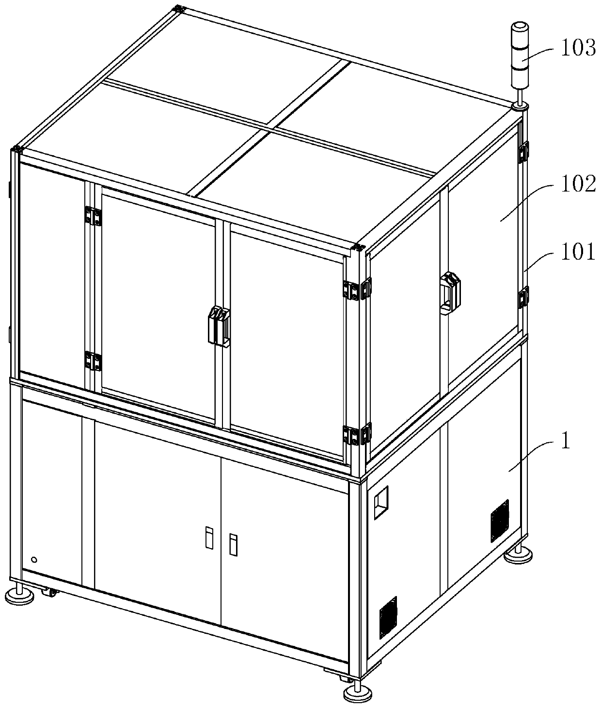
[0057] Embodiment: a kind of assembly equipment of coaxial connector, such as figure 1 As shown, it includes a workbench 1, the upper end of the workbench 1 is fixedly connected with a fixed frame 101, and a plurality of baffles 102 are hinged in the middle of the fixed frame 101. The baffles 102 can be opened to view the situation inside the workbench 1. The upper end of the workbench 1 An alarm 103 is provided, which can give an alarm when the work breaks down.

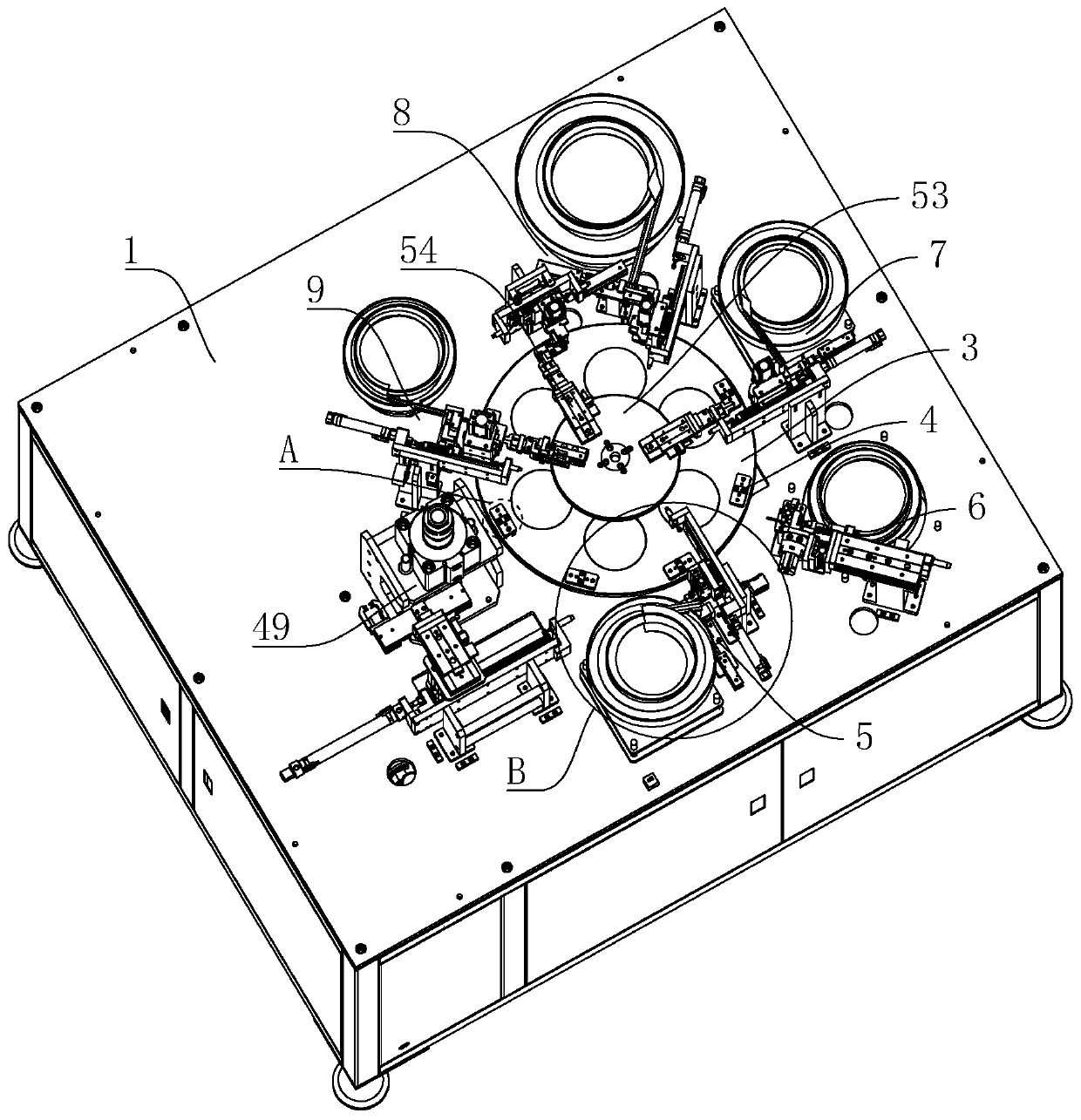
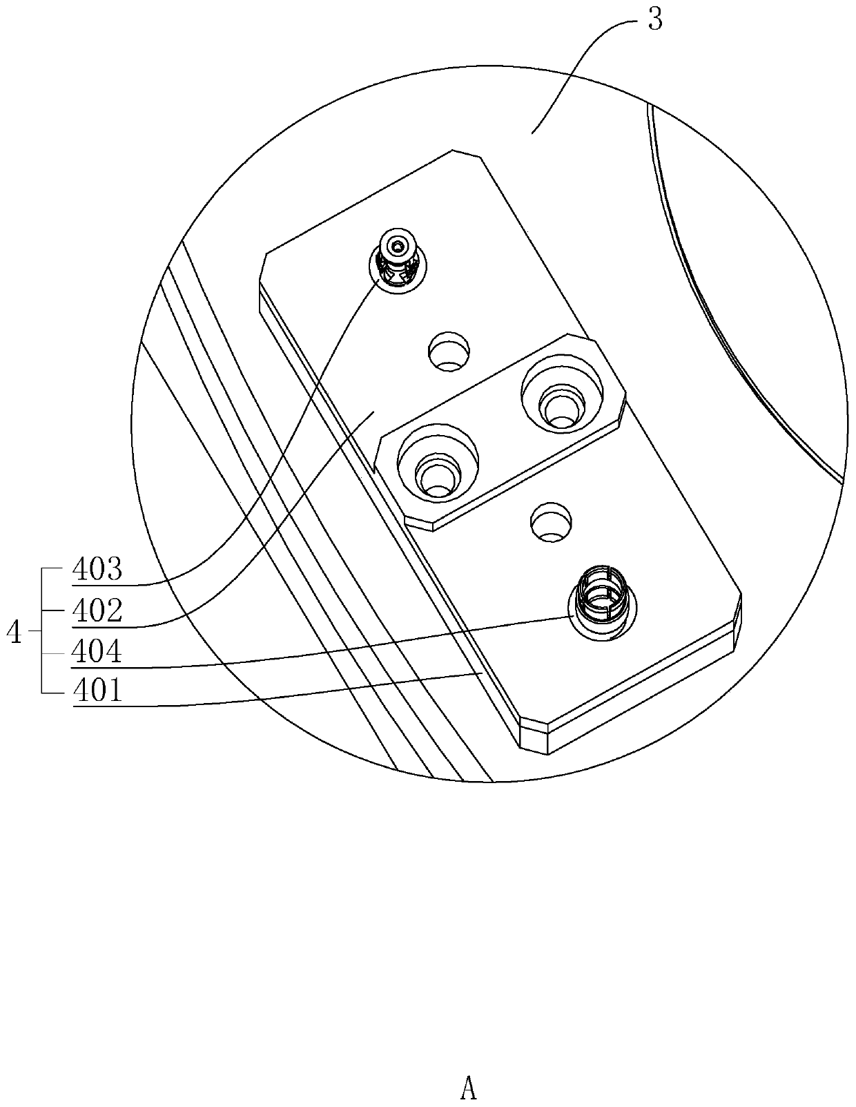
[0058] Such as figure 2 As shown, the upper end of workbench 1 is fixedly connected with drive motor 2 (refer to Figure 5 ), the drive motor 2 is linked with a drive turntable 3, and the upper end of the drive turntable 3 is provided with a plurality of fixtures 4. When assembling the coaxial connector, the drive motor 2 is started, and the drive motor 2 drives the drive turntable 3 to rotate intermittently. When it is time, it can drive the jig 4 to move intermittently.

[0059] Such as figure 2 As shown, th...

specific Embodiment approach

[0093] Specific implementation: when assembling the coaxial connector, place the lower insulator, the inner conductor, the upper insulator, the shell and the locking ring respectively on the lower insulator vibrating plate 501, the inner conductor vibrating plate 601, the upper insulator vibrating plate 701, Shell vibration plate 801 and locking ring vibration plate 901, and start the lower insulator vibration plate 501, the inner conductor vibration plate 601, the upper insulator vibration plate 701, the shell vibration plate 801 and the locking ring vibration plate 901, so that the lower insulator , Inner conductor, upper insulator, shell and locking ring vibration blanking.

[0094]Start the drive motor 2, and the drive motor 2 can drive the drive turntable 3 to rotate. When the drive turntable 3 rotates, it can drive the tooling fixture 4 to rotate. Component 6, upper insulator mounting component 7, shell mounting component 8, and locking ring mounting component 9 are link...


PUM


Abstract

The invention relates to assembling equipment for a coaxial connector. The assembling equipment comprises a workbench, the upper end of the workbench is fixedly connected with a driving motor, the driving motor is linked with a driving turntable, the upper end of the turntable is provided with a plurality of tool clamps, and the upper end of the workbench is provided with a lower insulator mounting assembly, an inner conductor mounting assembly, an upper insulator mounting assembly, a shell mounting assembly and a locking ring mounting assembly. When the tool clamps rotate, the lower insulatormounting assembly, the inner conductor mounting assembly, the upper insulator mounting assembly, the shell mounting assembly and the locking ring mounting assembly can be used for mounting and assembling a lower insulator, an inner conductor, an upper insulator, a shell and a locking ring in sequence; therefore, the coaxial connector can be automatically assembled, the precision of the automatically assembled coaxial connector is high, meanwhile, the assembling efficiency is greatly improved, and the labor force can be saved.

Description

technical field [0001] The invention relates to the technical field of connector assembly equipment, in particular to an assembly equipment of a coaxial connector. Background technique [0002] Coaxial connectors are used to transmit radio frequency signals, and their transmission frequency range is very wide, up to 18GHz or higher. They are mainly used in radar, communication, data transmission and aviation equipment. The basic structure of a coaxial connector includes: a central conductor (a male or female central contact); a dielectric material outside the inner conductor, or an insulator, and the outermost outer contact, which acts as the outer shield of the coaxial cable The same role as the layer, that is, to transmit signals, as a grounding element for shielding or circuits. In the past, this process can only be manually operated by workers, which not only wastes a lot of human resources, but also has low efficiency. [0003] There is an existing coaxial connector, ...

Claims


Application Information

Patent Timeline
IPC IPC(8): B23P21/00
CPCB23P21/006
Inventor 王兵王世昌张海亮夏正华
Owner 江苏吴通物联科技有限公司
Why Eureka
Try Eureka