
Processing device for smart phone

A processing device and smart phone technology, applied in positioning devices, clamping devices, metal processing, etc., can solve problems affecting processing quality, long production cycle, high labor cost, etc., to ensure accuracy and product quality, and avoid offset , The effect of ensuring accuracy

Active Publication Date: 2020-04-07
江苏金科森电子科技有限公司
View PDF5 Cites 1 Cited by
  • Summary
  • Abstract
  • Description
  • Claims
  • Application Information

AI Technical Summary

Problems solved by technology

At present, most of these production lines are manually operated, and the material is loaded by the operator. However, manual clamping not only has low precision and affects processing quality, but also has high labor costs, low efficiency, and long production cycles.

Method used


Image

  • Processing device for smart phone
  • Processing device for smart phone
  • Processing device for smart phone

Examples


Embodiment 1

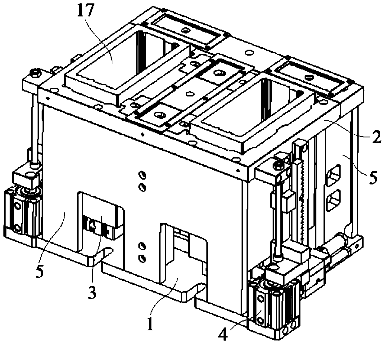
[0032]Embodiment 1: A processing device for smart phones, including a bottom plate 1, a top plate 2, a material seat 3 movably arranged between the bottom plate 1 and the top plate 2, and at least one pushing mechanism 4, the bottom plate 1 and the top plate 2 They are connected by several support plates 5, the ejector mechanism 4 is located on the side of the bottom plate 1, and the material seat 3 is provided with a material to be processed 17;

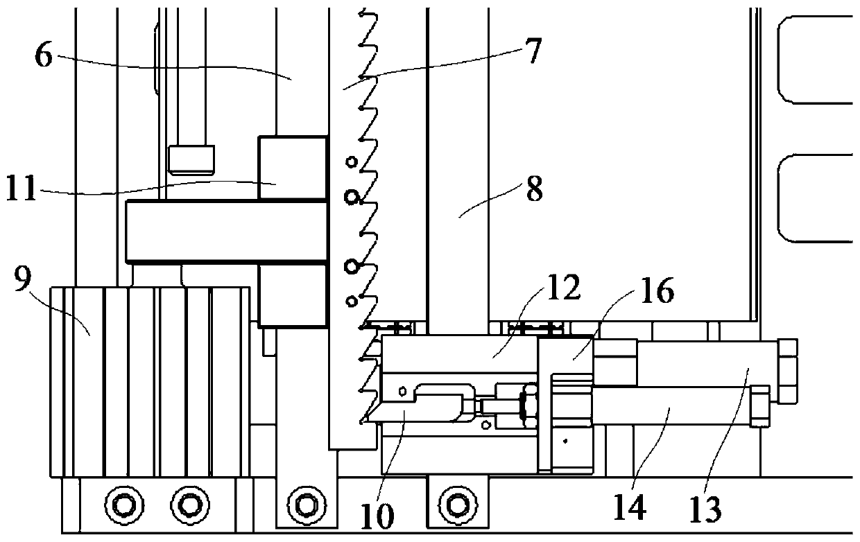
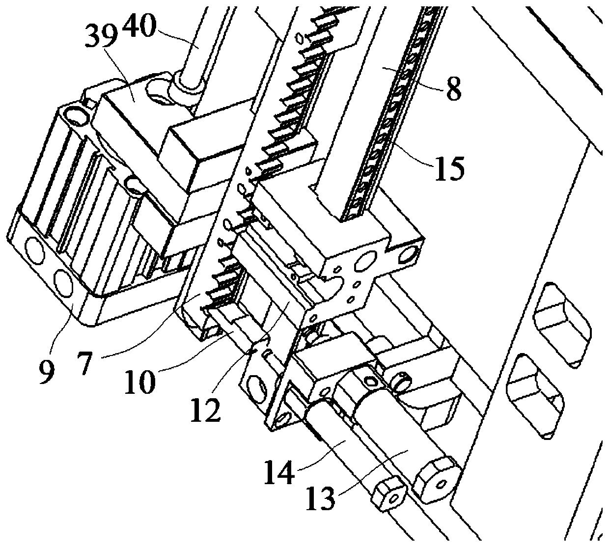
[0033] The ejector mechanism 4 further includes a guide post 6, a rack 7 movably mounted on the guide post 6, a positioning post 8, an ejector cylinder 9 and a snap-in tongue 10 for being embedded in the rack 7, the guide post 6 and the upper and lower ends of the positioning column 8 are respectively connected with the top plate 2 and the bottom plate 1, the rack 7 is movably connected with the guide column 6 through at least one slider 11, and the piston rod of the pushing cylinder 9 is connected with the slider 11 , for driving t...

Embodiment 2

[0039] Embodiment 2: A processing device for smart phones, including a bottom plate 1, a top plate 2, a material seat 3 movably arranged between the bottom plate 1 and the top plate 2, and at least one ejector mechanism 4, the bottom plate 1 and the top plate 2 They are connected by several support plates 5, the ejector mechanism 4 is located on the side of the bottom plate 1, and the material seat 3 is provided with a material to be processed 17;

[0040] The ejector mechanism 4 further includes a guide post 6, a rack 7 movably mounted on the guide post 6, a positioning post 8, an ejector cylinder 9 and a snap-in tongue 10 for being embedded in the rack 7, the guide post 6 and the upper and lower ends of the positioning column 8 are respectively connected with the top plate 2 and the bottom plate 1, the rack 7 is movably connected with the guide column 6 through at least one slider 11, and the piston rod of the pushing cylinder 9 is connected with the slider 11 , for driving ...


PUM


Abstract

The invention discloses a processing device for a smart phone. The processing device comprises a bottom plate, a top plate, a material seat movably arranged between the bottom plate and the top plate,and at least one pushing mechanism; the bottom plate and the top plate are connected through a plurality of supporting plates; the pushing mechanism is located on the side edge of the bottom plate; ato-be-processed material is arranged on the material seat; the pushing mechanism comprises a guide column, a rack movably installed on the guide column, a positioning column, an ejection air cylinderand a clamping tongue which is embedded into the rack; the upper ends and lower ends of the guide column and positioning column are connected with the top plate and the bottom plate respectively, therack is movably connected with the guide column through at least one sliding block; and the piston rod of the ejection air cylinder is connected with the sliding block. According to the processing device, the to-be-machined material placed on the material seat can be automatically fed; and therefore, manpower is replaced, processing efficiency is improved, errors of manual feeding can be avoided,processing precision is guaranteed, accidental injuries to workers can be avoided, and the automation level of equipment is improved.

Description

technical field [0001] The invention relates to the field of processing equipment for mobile phone parts, in particular to a processing device for smart phones. Background technique [0002] In the production line of industrial products, it is necessary to cut the finished product after completing one processing on the upper part of the material to be processed, and then process the material below. Therefore, the material to be processed must be loaded to enter the processing of the next layer of material. At present, most of these production lines are operated manually, and the material is loaded by the operator. However, manual clamping not only has low precision and affects the processing quality, but also has high labor costs, low efficiency, and long production cycles. Contents of the invention [0003] The object of the present invention is to provide a processing device for smart phones, which realizes the automatic loading of the materials to be processed placed on...

Claims


Application Information

Patent Timeline
IPC IPC(8): B23Q7/00B23Q3/08
CPCB23Q3/08B23Q7/006B23Q2703/04
Inventor 潘群曹银
Owner 江苏金科森电子科技有限公司
Learn More